")
items alternatives?
Hallo Per-Anders
I am not abble to order at Farnell but Mouser.
For the next couple of weeks
Panasonic EEU-FM1H102
and
ON Semiconductor 1N4007G
are not available.
Can I use:
Panasonic EEU-FM1H102B
and
Micro Commercial Components 1N4007GP-TP
instead of your listed items?
Hallo Per-Anders
I am not abble to order at Farnell but Mouser.
For the next couple of weeks
Panasonic EEU-FM1H102
and
ON Semiconductor 1N4007G
are not available.
Can I use:
Panasonic EEU-FM1H102B
and
Micro Commercial Components 1N4007GP-TP
instead of your listed items?
Hallo Per-Anders
Soldering is done. Same as the first try: I still have a steep learning curve ahead of me ;-(
The plan is to use 3x SSR03 (LM431) to get
1x 500mA@5V
2x 400mA@17V
I want to do this (complete analogue side of the DAC/ PreAmp project) with one Transformer. I like the concept of oversized linear PS. Is 50VA sufficient?
And the windings? 230Von one side is easy, but the second side? May I ask you to give me those two values, please?
Thank you and have a nice weekend!
Thank you!
Is there a formula or logic why the drop for the 17V PS is only 1V but for the 5V PS 4V?
Or is no TT below 9V available?
If so, do you have a reason for that?
What are the reasons to take the higher value (7V drop)?
I use a 18V TT for your 15V SSR03 ( LM329), too. Is that correct?
Is there a formula or logic why the drop for the 17V PS is only 1V but for the 5V PS 4V?
Or is no TT below 9V available?
If so, do you have a reason for that?
What are the reasons to take the higher value (7V drop)?
I use a 18V TT for your 15V SSR03 ( LM329), too. Is that correct?
Last edited:
The basic rule is that you'll get 1.4 times the AC rms voltage if you rectify and smooth the voltage. One more thing to consider is the open load voltage of the transformer. This voltage is higher for small transformers. If you read the datasheet of the transformer you can find out what the max output voltage to be. The goal for you is the have 5 V more at all time at the LM317/337 regulator. If you omit this pre-regulator then you'll gain 2.5 volts.
Hallo Per-Anders
Got my transformer yesterday and did some Tests with a 17V and 5V SSR03.
The TT should deliver 9V and 20V. I measured 8,5V and 19,7V under load. Always AC.
I do connect some resistors at the output of the SSR03 between "+" to gnd and "-" to gnd
10 ohm, 10W for the 5V SSR03
47 ohm, 10W for the 17V SSR03
I measured -3,16 and +3,20V DC respectively -14,26 and +14,36V DC under load. That's not enough ;-(
Where do I have to measure now to isolate the error?
Thank you
hallo Per Anders
one tip of the voltmeter on one or the other side of R9/10. but where do I put the second tip? ;-)
As written above:
The TT should deliver 9V and 20V. I measured 8,5V and 19,7V under load. Always AC.
Your output current?
TT/AC or SSR03 output/ DC?
I use a 100VA TT
How and where do i measure LM317/337 input and output?
LED's:
17V SSR03: both LED are on
5V SSR03: the two standad LED are on. the second pair is off
Last edited:
You wrote that you had 14.36 volts out but 17 volts unloaded? The LED should not be on if you don't have any regulation.
The input of the LM317 is the "IN" (please consult the schematics and datasheet of the part). The output is where you connect the load, terminal X3.
I want you to measure your incoming raw voltage and also identify the voltage drops so what is voltage between ground and R9, before and after? How heavy do you load the outputs? Is it with 10 and 47 ohms? => 300 mA
Hallo Per-Anders
I odered a100VA TT with 4x 20 - 0V and 2x 9V - 0 AC seconderys.
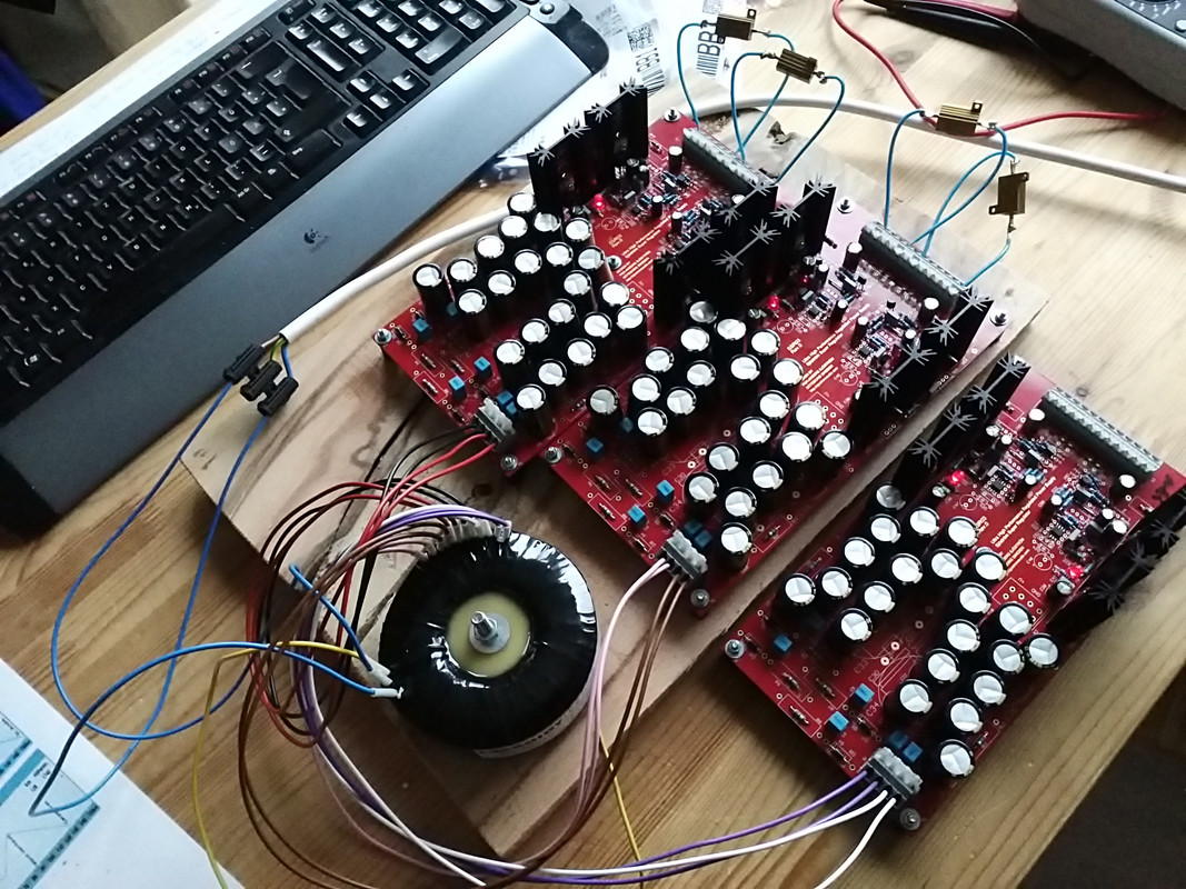
As you can see on the picture, at the X3 connectors I put some resistors between "+" to gnd and "-" to gnd
10 ohm, 10W for the 5V SSR03
47 ohm, 10W for the 17V SSR03
What I measure on the X1 connector is 8,5V and 19,7V with conneced load resistors at X3 as on the picture. Always AC.
At the X3 connectors I measured -3,16 and +3,20V DC respectively -14,26 and +14,36V DC parallel to the resistors.
Results:
@5v SSR03, with conneced load resistors as on the picture
X1:8,5V AC
x1-gnd -> R10: left 8,45 / right 7,72V DC
x1-gnd -> R9: 8,43 / 7,67V DC
X3: -3,16 and +3,20V DC
@17v SSR03, with conneced load resistors as on the picture
X1: 19,7V AC
x1-gnd -> R10: / V DC for a short period of time i get a number, but very quick I get 0.
x1-gnd -> R9: / V DC for a short period of time i get a number, but very quick I get 0
X3: -14,6 and +14,6V DC
the second 17V SSR03 I would like to discuss later...
Thank you
I odered a100VA TT with 4x 20 - 0V and 2x 9V - 0 AC seconderys.
As you can see on the picture, at the X3 connectors I put some resistors between "+" to gnd and "-" to gnd
10 ohm, 10W for the 5V SSR03
47 ohm, 10W for the 17V SSR03
What I measure on the X1 connector is 8,5V and 19,7V with conneced load resistors at X3 as on the picture. Always AC.
At the X3 connectors I measured -3,16 and +3,20V DC respectively -14,26 and +14,36V DC parallel to the resistors.
Results:
@5v SSR03, with conneced load resistors as on the picture
X1:8,5V AC
x1-gnd -> R10: left 8,45 / right 7,72V DC
x1-gnd -> R9: 8,43 / 7,67V DC
X3: -3,16 and +3,20V DC
@17v SSR03, with conneced load resistors as on the picture
X1: 19,7V AC
x1-gnd -> R10: / V DC for a short period of time i get a number, but very quick I get 0.
x1-gnd -> R9: / V DC for a short period of time i get a number, but very quick I get 0
X3: -14,6 and +14,6V DC
the second 17V SSR03 I would like to discuss later...
Thank you
- Status
- This old topic is closed. If you want to reopen this topic, contact a moderator using the "Report Post" button.
- Home
- Group Buys
- Group buy: SSR03 Super Regulator Power Supply Board