vvs07 & vitalica boards and parts posted.
JP
I received, ver-very beautifulPCB, thank you!
BR.
Quick status update from my side ...
I am still gathering parts:
- new transformer 2x20V 500VA just shipped from Toroidy. I already have a good +/- 19-20V supply in my curent Aleph build, but need to take that to +/- 24-25V.
- Set of Toshibas 2SJ201/2SK1530 won on eBay auction. Waiting for seller to ship.
- Want to use 0R33 source resistors for the Toshibas as per ZenMod recommendation in the thread "Official M2 schematic". Looking for Mundorf MResist MR5 0R33 2%, but selling company is closed for vacation until next week ... Ideally, I had wanted to use MPC74 resistors, but apparently, they are only made in 0R1 - 0R22 - 0R47 - 1R0, not 0R33. And I'm not keen on paralleling them.
On the progress side, yesterday I have measured and paired 2SJ74 / 2SK170. Also as per info on the "Official M2 schematic" thread, I have selected 2SJ74 with about 1 mA higher Idss than 2SK170. One pair is around 10.2 / 9.2 mA, the other around 8.3 / 7.5 mA. So it's 10% difference in each pair.
Major part of work in building my M2 will be heatsink alterations. The case I have and use right now I have built myself with heatsinks 160 mmm x 400 mm, using only frontplate and top from Modushop. So I need to take first one heatsink off and drill / tap it with the new mounting pattern, then remount it, then the other, in order not to disturb the custom alignment of all case parts ...")
Regards, Claas
I am still gathering parts:
- new transformer 2x20V 500VA just shipped from Toroidy. I already have a good +/- 19-20V supply in my curent Aleph build, but need to take that to +/- 24-25V.
- Set of Toshibas 2SJ201/2SK1530 won on eBay auction. Waiting for seller to ship.
- Want to use 0R33 source resistors for the Toshibas as per ZenMod recommendation in the thread "Official M2 schematic". Looking for Mundorf MResist MR5 0R33 2%, but selling company is closed for vacation until next week ... Ideally, I had wanted to use MPC74 resistors, but apparently, they are only made in 0R1 - 0R22 - 0R47 - 1R0, not 0R33. And I'm not keen on paralleling them.
On the progress side, yesterday I have measured and paired 2SJ74 / 2SK170. Also as per info on the "Official M2 schematic" thread, I have selected 2SJ74 with about 1 mA higher Idss than 2SK170. One pair is around 10.2 / 9.2 mA, the other around 8.3 / 7.5 mA. So it's 10% difference in each pair.
Major part of work in building my M2 will be heatsink alterations. The case I have and use right now I have built myself with heatsinks 160 mmm x 400 mm, using only frontplate and top from Modushop. So I need to take first one heatsink off and drill / tap it with the new mounting pattern, then remount it, then the other, in order not to disturb the custom alignment of all case parts ...
Regards, Claas
On the progress side, yesterday I have measured and paired 2SJ74 / 2SK170. Also as per info on the "Official M2 schematic" thread, I have selected 2SJ74 with about 1 mA higher Idss than 2SK170. One pair is around 10.2 / 9.2 mA, the other around 8.3 / 7.5 mA. So it's 10% difference in each pair.
Beware of the need to magnetically shield the signal transformer on the M2 to get good results. Otherwise, intolerable hum from EMI pickup from the mains power trafo to the small signal trafo. You can spend a lot of time matching FETs etc on M2, but it is all for naught with hum from EMI. Need mu-metal shield box or locate power trafo outside main case, or use SMPS PSU. That's my experience and for me, too much hassle so M2 is now out of the big Class A case for another amp,
Beware of the need to magnetically shield the signal transformer on the M2 to get good results.
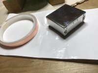
I have copper foil to make a belly band (Gauss band) for the little Edcor, and a steel Teko 3710 case (JP has designed the PCB to fit this case) for magnetic shielding.
Let's see how it goes ...
Best regards,
Claas
Attachments
Yes, and I am actually very curious about the outcome of the first approach to building the M2.
That's because my Aleph J-ish amp, whose power supply and case I will use, is actually the quietest amp I have so far built, restored, or even used.

I am using 100 dB/W-sensitive speakers, Jericho Horns, as seen in my avatar ...
Best regards,
Claas
That's because my Aleph J-ish amp, whose power supply and case I will use, is actually the quietest amp I have so far built, restored, or even used.
I am using 100 dB/W-sensitive speakers, Jericho Horns, as seen in my avatar ...
Best regards,
Claas
M2 Schematic resistor names need swapping
Just an update from my side:
I haven't started my build yet, still waiting for output MOSFETs and source resistors.
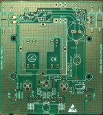
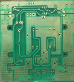
I did check the PCB thoroughly yesterday and found that, compared to the most current schematic that I have found (attached here again), the designations of two pairs of resistors need to be swapped to match the PCB.
This would be to swap the names of R114 with R125, and R113 with R122.
Maybe my schematic was outdated ...
All other designations, and all connections appear correct when I trace them.
Again, this is not changing the values, just the names, so that the names on the schematic match the ones on the PCB.
Hope this could avoid some confusion when populating the boards,
all the best, Claas
Just an update from my side:
I haven't started my build yet, still waiting for output MOSFETs and source resistors.
I did check the PCB thoroughly yesterday and found that, compared to the most current schematic that I have found (attached here again), the designations of two pairs of resistors need to be swapped to match the PCB.
This would be to swap the names of R114 with R125, and R113 with R122.
Maybe my schematic was outdated ...
All other designations, and all connections appear correct when I trace them.
Again, this is not changing the values, just the names, so that the names on the schematic match the ones on the PCB
.Hope this could avoid some confusion when populating the boards,
all the best, Claas
Attachments
Please remove my name (shown in red) I thought for some reason that this was a M2 POWER SUPPLY board. Apologies.
Brian
This supply pcb can be configured as either the old original Firstwatt powersupply (used in F5, M2 etc) or the newer power supplies that Nelson uses in F7 and F6.
To convert to either supply is just a matter of soldering in a link to convert to the original or leaving out the link to have the new supply.
Please @Soundhappy remove your reply from my thread then first I had never intention to offer this PCB for sale (I´m not competitor with Mr. Rothacher, please wait for his PCB availability in the store) and second, you can not affirm that this is a poor design only because not tested yet.
Thanks you!
JP
Thanks you!
JP
Just started up my first channel of M2 built on JPS64's boards. No problems in building it, and worked perfectly at first start-up.
I needed to re-drill and tap my heatsink, so it took me a bit to find the time (second one still to do).
I built it with Toshiba Laterals (2SK21530/2SJ201). So far, works very well, no issues with bias, offset, stability etc. Haven't listened to it yet, need to build second channel first.
One thing, probably coming from a resonance in the Edcor transformer: I'm seeing a small overshoot on 1 kHz and 10 kHz rectangle, has somebody else seen that ? (I should take that question to the M2 thread ...)
Thanks, Jean-Paul, for providing the boards !
Best regards,
Claas
Last edited:
Soundhappy,
I think JPS64 is a very talented layout designer. Perhaps one of the most energetic and generous. Look at all the designs he has produced for free to the community. On certain designs I assume he has asked permission of the original designer if he can do the GB. On the pocket headphone amp, he stopped the moment I asked him to as I am already selling them. So I don’t see any any motive here for sheer sales and profits at the expense of others. On my Aksa Lender preamp thread he has designed a very comprehensive layout with input selector, psu, motherboard and daughterboards of different varieties. A huge undertaking in my opinion. He has also asked Aksa for permission - have not heard back from Aksa yet. But being a public domain design that Aksa gave away for free - I don’t anticipate any issue.
Anyhow, I think as long as the projects he is having a GB had the approval of the original author - as a courtesy, it’s all good.
Regards,
X
Dear Soundhappy:
I have read a lot of posts from you in many threads, and I value your helpfulness in all your replies very much, and also your humour.
In this instance, I feel compelled to contribute my two cents as a participant in this Group Buy, please forgive me.
I have bought some sets of PCBs from JPS64 in this Group Buy.
In my case, it's for an M2, where no board is offered by the store, and for a couple of ACAs to build with my sons, where the store is curently out of boards.
The PCBs are very high quality and sturdy. I am currently building the M2, and that board works very well. With the quality and the size of the boards, you probably don't get them for USD 5 per board. The prices quoted to the participants in this group buy were per pair of boards.
Also, there is a lot of time involved in keeping track of payment from each member, packing, and shipping the boards.
I don't think JP is making a significant amount of money from this, if at all.
As far as I understand, he is working in the aerospace industry professionally. So, given his talents, if he wanted to make money, he could most probably spend his time much more effective than with layout-ing boards, ordering them, and offering them via a Group Buy.
Yes, JP is very prolific with his board layouts, but to me it looks more like an attempt to be of service to our community than an attempt to actually make money.
Kind regards,
Claas
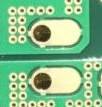
Seriously? Look at his wrong shape of the soldering pads.....
You are in team with JPS64 in PCB business.
Always makes promotion of your " products "for sale in PL forum section.
Preamp for sale, yeah! Sorry is not vendor bazar you don't understand is a thread about DIY amplifiers builds?
Please respect the rules don't hijack the threads with your selfish profit PCB's sales.
Best regards
Soundhappy (or is it Soundgrumpy), I think you are mistaken if you think I was offering a preamp for sale in Pass Labs forum. I only post specifically in threads to make people aware that there is a high voltage swing preamp available - it’s a free design. Please show me where I was tying to sell a preamp? The Aksa Lender preamp was made specially to be a DIYA free to the community design. If you bothered to look in the thread you will see all details of the circuit given and JP64 has also given away the layout Gerbers as well - all for free.
Not sure what the complaint is here for a solder pad for a cap, sure it should be bigger. Just use the one next to it. At least he has spade terminals instead of soldered flying leads for PSU and Speaker connections. That’s where the stress is going to be - not on a stationary cap leg wire.
Last edited:
JP, XRK,
I'm fine with JPS's excellent layouts and plans. I admire XRK and JPS for their energetic interest, outstanding skills and willingness to help others. This is a DIY forum and people must cooperate, not argue. It there is bad, public feeling the project will cease instantly and I do not believe that is in the interest of the members here.
This is indeed an open source project, but as soon as people have to build them, they are up for some cost. Selling the pcb for peanuts, knowing layout designer has spent many hours designing it, is trivial. To have JPS's skills on the layout in commercial arenas you would pay hundreds of euros. You cannot make things for nothing....... be reasonable, Soundhappy, and moderate your criticism. If you kick up again, I will ask the moderator to remove your posts.
Hugh
Hi JP,
may I know what is the usefulness of these asymmetric PCB pads (don't know the exact name for it) as seen in the attached picture, I just want to learn, thanks.
ps. keep up the good work, I like your PCB designs, they are both artistic and professional!
may I know what is the usefulness of these asymmetric PCB pads (don't know the exact name for it) as seen in the attached picture, I just want to learn, thanks.
ps. keep up the good work, I like your PCB designs, they are both artistic and professional!
Attachments
Yes, I think so.
Maybe it would be helpful to copy the first pages from Heathkit assembly manuals that detail what the parts look like and how to solder. A picture of an assembled PCB might be helpful to some as well. There will always be a couple folks who are overextending their abilities. They typically have the loudest voices.
-Chris
 Posts removed, please report any others that need to go.
- Home
- Group Buys
- My first GB