Recently got Trafo and BOM for Psu so stay tuned (just got to make time/priority)
For me output will be either DC1 or Sen but getting my head around CCS at the moment (but may just use Lampizator that is in my current DAC for the meantime so as just to get started)
Input will be basic - spdif using CS8412 etc. Until I can get my head around IanCanada I2S etc. And the buy it.
Hi Clayton,
I'm interested in what you're going to be using for your 26V supply. Ill attach what im using at the moment as it seems to do a great job at reducing ripple to levels I cannot see on my scope at all.
For the output stage I've just recently put in a Direct Coupled B-1 Buffer -Hypnotize after the CEN and it complements it very nicely, seems to drive my F5 Amp much better with absolutely no negative side effects. Bass sounds more controlled.
For my CEN 18V supplies im using a shunt reg similar to what's on my D2 pcb (TL431 with PNP pass transistor) and also using the same capacitance multiplier and filtering setup as the 26V supply which reduced the small amount of buzz/hum I had coming out of my speakers since I went from battery power to transformers.
Ryan
Attachments

Hey Ryan
Nothing too fancy for me here. For the 26v PSU initially it will be from parts that are on hand - so that means a LM317 reg with a CRC filter as per one of your previous posts - pretty basic for now just to get some power to the board. Your latest scheme will be under scrutiny now as well. I don't have a scope so will not be able to test ripple rejection etc. Not really worth it for this psu as we already know it will measure ok but not brilliant - be good enough to get the show on the road.
I notice all your suggestions for PSU utilise a CT and half rectifiers. I've got 2 X 12 so will put them in series and run into a full rectifier. and I worry because now you are going to tell me how that will not work or be a bad idea.
As I wrote previously I need to sort out a CCS for the output as well as the output stage.
I've also got a DCB1 Hypnotise recently (received in exchange for the CEN and heatsinks I traded on this thread earlier) and am looking forward to putting that together. I currently have a "pot in a box" passive pre that I have enjoyed but often feel the music is lacking in dynamics (?) and I am hoping the better impedance matching offered by the DC1 buffer will help with that. I am still trying to get my head around having DC coupled components in my setup as I am not sure it will play nice with all my sources - especially if I use a tube output stage from the DAC. (still reading on this topic because not sure if I understand what I am talking about or just speaking through a hole in the head.) Anyways, for now just enjoying new music purchased while on holiday (incl. a new discovery Curtis Harding), and through new cans and just last week completed a SSMH.
Nothing too fancy for me here. For the 26v PSU initially it will be from parts that are on hand - so that means a LM317 reg with a CRC filter as per one of your previous posts - pretty basic for now just to get some power to the board. Your latest scheme will be under scrutiny now as well. I don't have a scope so will not be able to test ripple rejection etc. Not really worth it for this psu as we already know it will measure ok but not brilliant - be good enough to get the show on the road.
Yeah It will be fine to get started, a few gains can be made if you make the effort here.
I notice all your suggestions for PSU utilise a CT and half rectifiers. I've got 2 X 12 so will put them in series and run into a full rectifier. and I worry because now you are going to tell me how that will not work or be a bad idea.
A full wave will be fine, if using the the LM317 just make sure you have enough voltage headroom I think you need about 3V across it.
As I wrote previously I need to sort out a CCS for the output as well as the output stage.
I'm going to try out another CCS soon, ill let you know how I go.
I've also got a DCB1 Hypnotise recently (received in exchange for the CEN and heatsinks I traded on this thread earlier) and am looking forward to putting that together. I currently have a "pot in a box" passive pre that I have enjoyed but often feel the music is lacking in dynamics (?) and I am hoping the better impedance matching offered by the DC1 buffer will help with that.
The higher the Zout the more the sound will be affected by things like interconnects and passive attenuators. From my experience with the DCB1, it only improves things. So you can look forward to things like better bass control and more realistic dynamics.
I am still trying to get my head around having DC coupled components in my setup as I am not sure it will play nice with all my sources - especially if I use a tube output stage from the DAC.
Does your tube output have an output cap? If so you'll be fine. Its starts becoming a bit more of a balancing act having a DC coupled system, thermal drifting is the biggest challenge, but I think its worth the effort. Caps in the signal path are only ever going to make it sound less transparent, adding their sonic signature/ colouring the sound. Not to say that it will sound bad, but to me it just takes you further away from what the recording is supposed to sound like.
new music purchased while on holiday (incl. a new discovery Curtis Harding), and through new cans and just last week completed a SSMH.
Nice! I like It. Although a little too much dynamic compression on the "Face your fear" album.
 such a pity. Although that's just my personal preference, maybe that's the sound they were going for - really loud and in your face with no dynamics... maybe not. Nice build by the way!
Keep us updated on your progress.
Ryan
Last edited:
I'm interested in what you're going to be using for your 26V supply. Ill attach what im using at the moment as it seems to do a great job at reducing ripple to levels I cannot see on my scope at all.
Hey Ryan
What are you using for the transistors in this psu? Anything special?
As I've got BC550 and BC560 in my parts box I might have a go at the psu you have in this post rather than just the lm317 one. Just be needing a few different inductors as I only have 10u on hand
Hey Ryan
What are you using for the transistors in this psu? Anything special?
As I've got BC550 and BC560 in my parts box I might have a go at the psu you have in this post rather than just the lm317 one. Just be needing a few different inductors as I only have 10u on hand
Hey there,
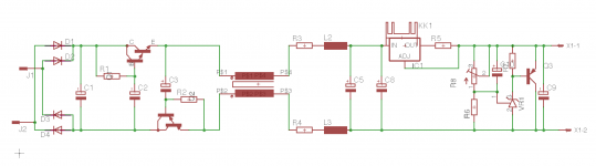
The transistors I used are the BD680 and B679, which are darlington power transistors, the current gain is around 1000. In the schematic I posted earlier, the 100mH inductors are actually a common mode choke (Part link)
For the diffrential chokes, I was thinking something like this (Part link)
The BC550/60 might get a tad hot, if you did go this option, check out the internal schematic of the BD680/70, as there is a few resistors internally. (its listed here or its in the data sheet.) Its easier to just use the darlingtons in my opinion, but you could possibly get better results using separate transistors, not sure.
You may like to try without the inductors first and just use an RC after the CapMx to drop the voltage to between 26 - 27V. You should get around 500uV peak to peak ripple this way. With the inductors Im seeing nothing at all, its buried by the noise floor at 250uV. I need a better scope for low noise stuff, mine only goes down to 2mV per division, so those numbers are just approx.
Hi Ryan
That R2 of 200r on the rh side of your Psu schematic - is that just a load for your measurements, or part of the circuit?
Do you have heatsinks on these Darlingtons?
Thanks
Clayton
Hi Clayton,
R2 was just to simulate the load. No need for heatsinks on the darlingtons they only get a little warm with this current load.
Nice to see your giving it a go.
Hi Clayton,
R2 was just to simulate the load. No need for heatsinks on the darlingtons they only get a little warm with this current load.
Nice to see your giving it a go.
Be a few weeks yet. Have to wait for a work colleague to be travelling to/from somewhere that is easier to access parts otherwise duties too much on a Mouser order to me here. Thanks for your help.
Another question - looking ahead to making the CCS
- I see that you have test points on the V2 board for -15, +5, -5. Is it possible to draw current from these for the CCS?
else I'm up for another two psu/regulators to join the 26v and 8v for the DAC, 18v for each channel of SEN I/V, 2 x 5v for receiver
cheers
- I see that you have test points on the V2 board for -15, +5, -5. Is it possible to draw current from these for the CCS?
else I'm up for another two psu/regulators to join the 26v and 8v for the DAC, 18v for each channel of SEN I/V, 2 x 5v for receiver
cheers
Another question - looking ahead to making the CCS
- I see that you have test points on the V2 board for -15, +5, -5. Is it possible to draw current from these for the CCS?
else I'm up for another two psu/regulators to join the 26v and 8v for the DAC, 18v for each channel of SEN I/V, 2 x 5v for receiver
cheers
Yes, you can do this, that's one of the reasons I put them there. Im taking 4mA from the +5V supply for my CCS. If you use the -5V just be aware that i've labeled it backwards, GND and -5V should be swapped around. Also note that the more current you take from these supplies the more you are effectively increasing the output impedance, but a few mA shouldn't hurt it much.
Yes, you can do this, that's one of the reasons I put them there. Im taking 4mA from the +5V supply for my CCS. If you use the -5V just be aware that i've labeled it backwards, GND and -5V should be swapped around. Also note that the more current you take from these supplies the more you are effectively increasing the output impedance, but a few mA shouldn't hurt it much.
Thanks. Very convenient.
separate CCS for each channel right?
Thanks. Very convenient.
separate CCS for each channel right?
Yes, a separate 2mA ccs for each channel.
FFT of Cap MX
Hi All,
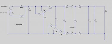
Just been playing around in the shed trying to get some meaningful measurements from the cap MX circuit I posted in post #101. (attached here also)
I injected 1V RMS signal sweep from 100hz to 1Mhz into the input of the circuit.
Circuit under test was powered from a DC source with a load attached.
The filter cap (C1) was removed for the test as it provided an impedance way too low for the amplifier I was using to handle, I think I had about 11ohm zout.
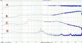
The attached image shows the levels measured at various points in the circuit.
A - Signal sweep input (where C1 was)
B - C6
C - C7 and C4 had very similar levels.
D - This is the noise floor of the measuring system with the settings I had on. It was also the same output level as when the circuit under test was being powered by the rectifier with the filter cap in place.
When you consider these measurements plus a 2200uF filter cap added to the start of the circuit, it seems to have quite an ample amount of Noise/Ripple rejection before the Voltage reg/CCS of the D2 PCB.
Ill give it a bit more thought but i've already started laying out a PCB so if anyone's interested in one just start a list in this thread. eg: "ryanj x 1 capmx pcb" and ill get a few extras made up.
These measurements are obviously a fairly amature attempt, but it at least gives some indication of what is going on in the circuit.
Ryan.
Hi All,
Just been playing around in the shed trying to get some meaningful measurements from the cap MX circuit I posted in post #101. (attached here also)
I injected 1V RMS signal sweep from 100hz to 1Mhz into the input of the circuit.
Circuit under test was powered from a DC source with a load attached.
The filter cap (C1) was removed for the test as it provided an impedance way too low for the amplifier I was using to handle, I think I had about 11ohm zout.
The attached image shows the levels measured at various points in the circuit.
A - Signal sweep input (where C1 was)
B - C6
C - C7 and C4 had very similar levels.
D - This is the noise floor of the measuring system with the settings I had on. It was also the same output level as when the circuit under test was being powered by the rectifier with the filter cap in place.
When you consider these measurements plus a 2200uF filter cap added to the start of the circuit, it seems to have quite an ample amount of Noise/Ripple rejection before the Voltage reg/CCS of the D2 PCB.
Ill give it a bit more thought but i've already started laying out a PCB so if anyone's interested in one just start a list in this thread. eg: "ryanj x 1 capmx pcb" and ill get a few extras made up.
These measurements are obviously a fairly amature attempt, but it at least gives some indication of what is going on in the circuit.
Ryan.
Attachments
Last edited:
LM317 PSSR Comparison
Hi All,
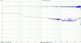
After testing the Cap MX I was a little curious how the LM317 would fare under similar circumstances.
Very similar test setup as the Cap MX, same load, same voltage drop and no input cap. I didn't quite get the same input signal sweep voltage of 1V RMS in to the circuit due to amplifier limitations, so just take note of the difference between the input(top) and output(bottom) FFT.
Overall it looks like the LM317 does well in the high frequencies but not so well in the lower/audible range.
Ryan.
Hi All,
After testing the Cap MX I was a little curious how the LM317 would fare under similar circumstances.
Very similar test setup as the Cap MX, same load, same voltage drop and no input cap. I didn't quite get the same input signal sweep voltage of 1V RMS in to the circuit due to amplifier limitations, so just take note of the difference between the input(top) and output(bottom) FFT.
Overall it looks like the LM317 does well in the high frequencies but not so well in the lower/audible range.
Ryan.
Attachments
I notice all your suggestions for PSU utilise a CT and half rectifiers. I've got 2 X 12 so will put them in series and run into a full rectifier. and I worry because now you are going to tell me how that will not work or be a bad idea.
Hello again
Am I correct thinking that if I apply your schematic for the 24v PSU to a full rectification I omit the PNPs etc on the negative rail?
Also I am confused generally with transformers eg. 24CT could be made using 2 x 12v windings given the right trafo - correct? you dont use 2 x 24v to make 24ct because that would give 48vCT. I need to have a closer look at my transformer to see what is possible (I'm currently away from home)
Received some parts this week courtesy of a colleague who was travelling out of the US - had them delivered to his as he was coming my way to attend a training event but he was only travelling with carry-on and got hassled at security travelling through Qatar - I had not anticipated that a couple of transformers, pin connectors, common mode chokes and cable glands would cause issue - no sharps, no liquids etc. - stuff I expect you would see in carry-on normally as people carry power supplies for their laptops etc. (just not as individual parts) thankfully they let it pass.
Expecting additional parts to arrive any day now so that I can get on with this - I have started hand milling pcbs using an engraving bit set to depth on the drill press of my rotary tool and am reasonably happy with the results on simple boards for PSUs and a TDA1543 project (parallel and single). I also note that ECdesigns has made new design suggestions on the "ultimate NOS dac" thread using 14X 100uf coupling caps - might play with that to.
Too many projects, too little time.
Hi Clayton,
You dont need to omit the PNP darlington if you use 4 diodes and a single 24V winding, it will work pretty much the same except you'll get the voltage drop of the extra diode in the current path. Which won't be very much if using schottky diodes.
Yep that's right.
Doubt they even new what they were. Probably not something they see much as they are normally covered by a plastic case. Good you ended up getting them anyway.
Yeah I saw that. Running the DEM at 50Hz means each sample is not going to get the same bit current averaging. Maybe in doing this he is basically saying that the DEM does more damage to the internal timing circuit than it does good. It may be a case of choosing the approach that causes the least
amount of damage to the final output signal.
You're a real diyer! The "Toner transfer method" for making PCBs was my favorite. I wouldn't mind getting a CNC router to make PCBs, would cut out the waiting time getting them from a board house when making prototypes.
Ryan
Am I correct thinking that if I apply your schematic for the 24v PSU to a full rectification I omit the PNPs etc on the negative rail?
You dont need to omit the PNP darlington if you use 4 diodes and a single 24V winding, it will work pretty much the same except you'll get the voltage drop of the extra diode in the current path. Which won't be very much if using schottky diodes.
Also I am confused generally with transformers eg. 24CT could be made using 2 x 12v windings given the right trafo - correct? you dont use 2 x 24v to make 24ct because that would give 48vCT.
Yep that's right.
Received some parts this week courtesy of a colleague who was travelling out of the US - had them delivered to his as he was coming my way to attend a training event but he was only travelling with carry-on and got hassled at security travelling through Qatar - I had not anticipated that a couple of transformers, pin connectors, common mode chokes and cable glands would cause issue - no sharps, no liquids etc. - stuff I expect you would see in carry-on normally as people carry power supplies for their laptops etc. (just not as individual parts) thankfully they let it pass.
Doubt they even new what they were. Probably not something they see much as they are normally covered by a plastic case. Good you ended up getting them anyway.
I also note that ECdesigns has made new design suggestions on the "ultimate NOS dac" thread using 14X 100uf coupling caps - might play with that to.
Yeah I saw that. Running the DEM at 50Hz means each sample is not going to get the same bit current averaging. Maybe in doing this he is basically saying that the DEM does more damage to the internal timing circuit than it does good. It may be a case of choosing the approach that causes the least
amount of damage to the final output signal.
Expecting additional parts to arrive any day now so that I can get on with this - I have started hand milling pcbs using an engraving bit set to depth on the drill press of my rotary tool and am reasonably happy with the results on simple boards for PSUs and a TDA1543 project (parallel and single).
You're a real diyer! The "Toner transfer method" for making PCBs was my favorite. I wouldn't mind getting a CNC router to make PCBs, would cut out the waiting time getting them from a board house when making prototypes.
Ryan
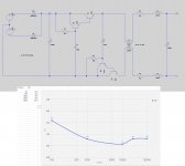
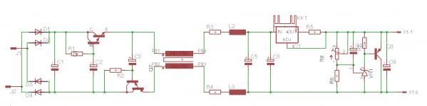
Hi guys,
Attached is a schematic of the cap MX circuit that I ended up with after testing. Also attached a basic ripple rejection graph of the measurements I took.
The previous measuring setup I had (Virtins multi-instrument) seemed to give me differing results each time, so I used my scope instead using a differential measuring technique. Here's a link to one of Dave Jones videos that describes the technique I used: YouTube
Test setup was the same as before but using my scope to analyse the waveform instead.
I had a short listen to my system with this circuit in place and its sounding like i've gained some improvement in sound quality, Ill have a better listen soon.
Attachments
Last edited:
PSU
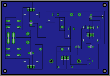
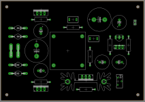
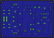
Following on from setting up PSUs to feed the Distinction board and, for me, a CEN output stage.
For the CEN I will use Ryan's CapMx and some LM317/TL417 regulation. I will make the attached by hand milling the boards, as per a previous post - so have designed a layout that allows for single sided pcb. The CapMx board will be of course much simplified.
Thought I would post these before I set to making them - part selection according to my own BOM of course, leaving no options for different part sizes.
Attachments
Doh!
Just noticed R2 on the pnp is on the wrong side - thought I had fixed this earlier
Disregard my last post - Be right back with corrected version
Just noticed R2 on the pnp is on the wrong side - thought I had fixed this earlier
Disregard my last post - Be right back with corrected version
Attachments
Last edited:
- Status
- This old topic is closed. If you want to reopen this topic, contact a moderator using the "Report Post" button.
- Home
- Group Buys
- Distinction-1541 v2 complete PCB interest list