Hi guys,
Just on the issue of i2s / simultaneous data input:
If you want to go for I2S in the beginning then later on try simultaneous - no problem, ill include the parts so you can change it over, its only 3 resistors and also changing the data input selector.
I2S setup:
BCK will not be attenuated - 0R jumper on R6 (the input resistor for BCK) and leave out R4 and R8.
WS will be left as a diode attenuator.
DATA L/R will be left as a resistive attenuator.
My post a while back talking about my preferences on attenuation.
Schematics
Ryan
Ok Ryan i will start with only i2s because i already have a board for that.Hi guys,
Just on the issue of i2s / simultaneous data input:
If you want to go for I2S in the beginning then later on try simultaneous - no problem, ill include the parts so you can change it over, its only 3 resistors and also changing the data input selector.
I2S setup:
BCK will not be attenuated - 0R jumper on R6 (the input resistor for BCK) and leave out R4 and R8.
WS will be left as a diode attenuator.
DATA L/R will be left as a resistive attenuator.
My post a while back talking about my preferences on attenuation.
Schematics
Ryan
Than later i will switch to simultaneous.
Do i need to send a message or you dont forget?
Regards
26V supply examples
Hi Guys,
A few people have messaged me with queries about how to power the 26V floating supply.
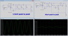
Here are a two examples I put together that may give you a starting point. One with a RC + darlington capacitance multiplier, and the other a standalone RC filter for comparison. Both have a full-wave center-tapped diode config.
I'm not sure how accurate the modeling is as I have not built these so please do your homework before attempting to put this together. Please ignore the 1 MEG resistor to ground, they are only there to give the program a reference point. If I modeled these circuits with the "zenner string", it would have the ground reference between +5V and -5V and wouldn't need it in this position. The inputs for the 26V supply are not referenced to ground!
Transformers were modeled as 25V + 25V, you may want more headroom or less, its up to you. I would suggest getting a cheap transformer first. Then later find one with good isolation between the primary and secondary windings to reduce capacitive coupling to ground (the neutral wire is connecting to ground).
Schottky diodes are modeled, but you could go for standard silicon but just allow for the higher voltage drop.
Lastly, I'd just like to point out that there are probably hundreds of discussions on this very topic right here on diyaudio, so have a read! and be creative! =)
Cheers,
Ryan
Hi Guys,
A few people have messaged me with queries about how to power the 26V floating supply.
Here are a two examples I put together that may give you a starting point. One with a RC + darlington capacitance multiplier, and the other a standalone RC filter for comparison. Both have a full-wave center-tapped diode config.
I'm not sure how accurate the modeling is as I have not built these so please do your homework before attempting to put this together. Please ignore the 1 MEG resistor to ground, they are only there to give the program a reference point. If I modeled these circuits with the "zenner string", it would have the ground reference between +5V and -5V and wouldn't need it in this position. The inputs for the 26V supply are not referenced to ground!
Transformers were modeled as 25V + 25V, you may want more headroom or less, its up to you. I would suggest getting a cheap transformer first. Then later find one with good isolation between the primary and secondary windings to reduce capacitive coupling to ground (the neutral wire is connecting to ground).
Schottky diodes are modeled, but you could go for standard silicon but just allow for the higher voltage drop.
Lastly, I'd just like to point out that there are probably hundreds of discussions on this very topic right here on diyaudio, so have a read! and be creative! =)
Cheers,
Ryan
Attachments
Hi Guys,
A few people have messaged me with queries about how to power the 26V floating supply.
Here are a two examples I put together that may give you a starting point. One with a RC + darlington capacitance multiplier, and the other a standalone RC filter for comparison. Both have a full-wave center-tapped diode config.
I'm not sure how accurate the modeling is as I have not built these so please do your homework before attempting to put this together. Please ignore the 1 MEG resistor to ground, they are only there to give the program a reference point. If I modeled these circuits with the "zenner string", it would have the ground reference between +5V and -5V and wouldn't need it in this position. The inputs for the 26V supply are not referenced to ground!
Transformers were modeled as 25V + 25V, you may want more headroom or less, its up to you. I would suggest getting a cheap transformer first. Then later find one with good isolation between the primary and secondary windings to reduce capacitive coupling to ground (the neutral wire is connecting to ground).
Schottky diodes are modeled, but you could go for standard silicon but just allow for the higher voltage drop.
Lastly, I'd just like to point out that there are probably hundreds of discussions on this very topic right here on diyaudio, so have a read! and be creative! =)
Cheers,
Ryan
Hi Guys,
This is an important issue for the untrained like me: I can solar what they tell me, but I don't design a floating supply. If anyone has a definitive design on this I will be very grateful.
Thanks a lot
Hi Guys,
This is an important issue for the untrained like me: I can solar what they tell me, but I don't design a floating supply. If anyone has a definitive design on this I will be very grateful.
Thanks a lot
Cannot use a standar linear power supply?
- Status
- This old topic is closed. If you want to reopen this topic, contact a moderator using the "Report Post" button.
- Home
- Source & Line
- Digital Line Level
- TDA1541A Diy Pcb - "Distinction-1541 v2"