Here it is:
NZ2520SDA Group buy
(for 22.5792 MHz, 24.576 MHz, 45.1584 MHz and 49.152 MHz oscillators):
1. M_Baou - 1 pair of 4x.
2. sontero - 1 pair of 4x.
3. kvl - 2 pairs of 4x.
4. wlowes - 1 pair of 4x.
5. aguaazul: 1 pair of 4x.
I'll send you a PM in a couple of minutes, thanx!
EDIT: Walter and aguaazul: you have PMs!
Last edited:
With welcome! I hope the packaging was okay? I suppose your parts are intact?
Does ANY of you had at least one oscillator delivered in damage condition? I ask this because there was a customer of mine saying his both oscillators were delivered with the metallic can bent inside the part = towards the crystal oscillator and the silicon chip. I said that in my opinion this is not possible unless in some fictional, extraordinary cases. Anyway, since I don't know how good my package method was I thought I should ask you for your opinions!
Thank you,
L
EDIT: my beliefs are tied to a very bad soldering procedure = parts exposed to excessive heat for a long time BUT, in my experience where I manually solder more than 2000 pcs. I NEVER hit this "performance" to bend the metallic can!
Does ANY of you had at least one oscillator delivered in damage condition? I ask this because there was a customer of mine saying his both oscillators were delivered with the metallic can bent inside the part = towards the crystal oscillator and the silicon chip.
I said that in my opinion this is not possible unless in some fictional, extraordinary cases. Anyway, since I don't know how good my package method was I thought I should ask you for your opinions!Thank you,
L
EDIT: my beliefs are tied to a very bad soldering procedure = parts exposed to excessive heat for a long time BUT, in my experience where I manually solder more than 2000 pcs. I NEVER hit this "performance" to bend the metallic can!
Last edited:
WOW!! This is the real deal.
This report by Extreme_Boky encouraged me to upgrade from the SD version. I echo his observations and those of others in this thread who have reported similar experiences.
It is not a subtle improvement. One of those OMG moments. I have to listen to my entire collection again. Soundstage is precise. More natural. Individual sources hang in 3d space some how independent from others. I do not experience a subjective loss in high frequencies. If anything symbols are more natural and apparent.
This is the best bang for the buck upgrade available.
One tip. As with the SD variant, great power and vibration dampening brings great rewards. I place a small blob of putty right over the oscillator. I also solder a really good cap as close as possible to the V+ pad. In my case a Blackgate HiQ 0.47u did the trick. I initially listened to the system without these adds. The sound was great but lacked the rich smooth micro details that appear with the add of the putty & cap. The power supply is already very good dedicated supply and overall vibration dampening was pretty well done... still give it a try.
Thanks Lorien. Once again, you have been instrumental in taking my system to the next level.
... much better instrument's definition and faithfulness to how they should sound. The micro-detail retrieval is also much better. The bass frequencies definition and reach is miles ahead compared to SD board. The bass is also much deeper; I'd say that subjectively, the bass gained a lot in energy and in particular in definition.
Human voices are also much more natural. I played both boards to my friends (a tough and critical bunch of high enders and professional musicians) and my kids, and they were all stunned at the improvement SDA boards provides.
There is an improved sense of darker background / better dynamic range. This is easily noticeable, compared to SD board. The music has better flow and better engagement with an SDA board. ....
.
This report by Extreme_Boky encouraged me to upgrade from the SD version. I echo his observations and those of others in this thread who have reported similar experiences.
It is not a subtle improvement. One of those OMG moments. I have to listen to my entire collection again. Soundstage is precise. More natural. Individual sources hang in 3d space some how independent from others. I do not experience a subjective loss in high frequencies. If anything symbols are more natural and apparent.
This is the best bang for the buck upgrade available.
One tip. As with the SD variant, great power and vibration dampening brings great rewards. I place a small blob of putty right over the oscillator. I also solder a really good cap as close as possible to the V+ pad. In my case a Blackgate HiQ 0.47u did the trick. I initially listened to the system without these adds. The sound was great but lacked the rich smooth micro details that appear with the add of the putty & cap. The power supply is already very good dedicated supply and overall vibration dampening was pretty well done... still give it a try.
Thanks Lorien. Once again, you have been instrumental in taking my system to the next level.
This report by Extreme_Boky encouraged me to upgrade from the SD version. I echo his observations and those of others in this thread who have reported similar experiences.
Luck has a lot to do with what this SDA upgrade will do at the end... I was lucky with the first board I upgraded with SDA's, but unlucky with the second board.
The second board I received back sounded quite bad compared with the first one, unfortunately. I can't use it.
The low phase oscillators need to be measured and selected from the tape reel... and only those that do provide a good measurement should be used - otherwise, it's a gamble.
Last edited:
Good heads up!
Thanks for more useful insight. This seems consistent with everything I have read. Based on a small sample on this thread, it seems there is a fairly high % of good ones on a reel. Both my 45mhz and 49mhz oscillators were a major step up over the SD versions.
If you are willing to take the leap of faith and solder these things, I think it would be worth the $ to roll the dice and put them in knowing you may fail based on a sample that is off typical spec, or if you simply destroy it with too much heat. I think going into this you have to be prepared to fail and repeat your effort and possibly buy more parts than planned. It would be really easy to literally lose one as they are tiny and can really take flight if your tweezers lose grip. Still in the end, at $15 per part, you can afford to buy a couple as the performance appears to best a lot more expensive parts.
My 49mhz clock soldered first attempt and worked perfectly. My 45mhz clock eluded my soldering efforts for several attempts. That meant I could play 96 and 192 material but the vast majority of 44.1 material was a no go. I seriously thought I had fried the 45mhz part, but on close examination it appeared that one pad was not accepting solder. A little rosin and I was in business. I was prepared to reinstall the SD chip while waiting a replacement. A reasonable alternative would be to buy a couple of the critical 45mhz part just in case as it can fail in multiple ways.
1. you just plain lose the little devil,
2. you fry it, or as you discovered,
3. it works but is one of the small sample of low spec parts
BTW, the parts I found useful to successfully solder are:
1. a jewelry loop. 10x magnification required to read the etching and inspect the solder joints,
2. really good needle nose tweezers. I have the ones that are 30 degree angle
3. fine tipped soldering iron,
4. air station. In my case I took a regular heat gun, and fashioned a nozzle the size of the part using a tube of aluminum foil clamped on the heat gun and onto my nozzle which was a small socket from my wrench kit. Then practiced on an old junk PCB with lots of small parts to get a sense of how long it takes to heat up to remove/replace parts. Turns out on low heat you can heat up the area and then ramp up fast on high for a few seconds. I think it more or less simulated the specified heat ramp profile.
The other tip was provided by another poster suggesting that you attach a piece of masking tape sticky side up to your bench to secure the part while you tin the pads.
Lorien's suggestion to place a little heap of solder on each pad was really great. I then found it easy to tag the part down on one pad with the iron, and then use the air station to seat the entire part.
Lastly I found it useful to mark one side of the part so you can see how to orient it without the 10x loop. For my old eyes, the little dot on the part and the etching is darned near invisible.
Attachments
Can anyone tell me if the SDA can be soldered on one of the Twisted Pear Rhea modules?
Cronus Reclocking
I have the Cronus reclocker between my DSC2.5 and BBB/Hermes and I wonder if I’d be able to upgrade the CCHD-957 clocks.
Cronus Reclocking
I have the Cronus reclocker between my DSC2.5 and BBB/Hermes and I wonder if I’d be able to upgrade the CCHD-957 clocks.
@ Extreme_Boky: I had a weak feeling it would be like this but never had the chance to be confirmed till now. I'll seek the opportunity to buy some gears (which I don't have now) to measure them before selling them but so far have no clear idea how I should do it or how much money this new 'adventure' will cost me since I'm sure those gears are not "dirt cheap"!
OTOH, I tried to contact you over PMs but got no reply from you (yet).
@ luchoh: looking at the pictures in your link it seems that you'll need two adapter PCBs (which I can't provide for now - I'm sorry!). All the distances found there are too big for the SDA oscillators to fit without adapter and playing with wires it will be a close to nightmare job. I don't say it can't be done but I strongly suggest against it!
@ Sligolad: yes they are available! I'll PM you in a couple of seconds! Thank you!
So I can attest to the nightmare of using wire to attempt an installation onto a board that once had a larger clock on it.
I’m afraid it has cost me a single device, and will not be using that one. I will need to order another and find an adapter board solution as well. Unless you are upgrading a cell phone, these probably won’t do you much good as is.
Actually will just leave my project alone for now, been a really bad week here, and not wise to attempt any heroic soldering for a while I’m afraid.
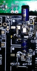
So the pad that I thought I had lifted was intact, and I mounted it to a fabricated breakout board, thought that was some good news.
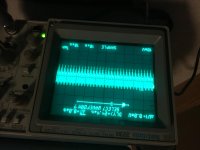
I powered it up and it makes an asymmetrical wave form of sorts.
Any ideas what is going on? I’m new to oscillator circuits, intentional ones anyways.
I powered it up and it makes an asymmetrical wave form of sorts.
Any ideas what is going on? I’m new to oscillator circuits, intentional ones anyways.
Attachments
- Status
- This old topic is closed. If you want to reopen this topic, contact a moderator using the "Report Post" button.
- Home
- Group Buys
- NDK NZ2520SDA oscillators group buy