Received, thanks.
BTW, for those who are replacing larger oscillators and not using adaptor boards (I did one this size last year), here are some tips:
BTW, for those who are replacing larger oscillators and not using adaptor boards (I did one this size last year), here are some tips:
- Use a VERY SMALL tipped soldering iron. NOT a gun, NOT a fat-tipped iron.
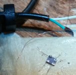
- Put some masking tape, sticky-side up on the work bench, then tape the ends of that tape down to the bench. Stick the oscillator to the exposed sticky part, contacts facing up. Don't let it get loose, it can be very difficult to find it if it goes flying!
- find some very fine wires (such as you might find in a multistranded wire inside some earphone cables). Pull out a single strand about 5mm long with tweezers, and pre-tin one end with solder. This wire can not be too thin!
- Tack solder the pre-tinned wire to the contact on the bottom of the oscillator. Repeat for the other contacts of the oscillator
- Then carefully pull the package off the tape and drop it onto its final location
- Use tweezers to drag the fine wires to the connection pads and quickly solder them down. Don't worry about length or routing, they are too short to worry about
")
Received, thanks.
BTW, for those who are replacing larger oscillators and not using adaptor boards (I did one this size last year), here are some tips:
- Use a VERY SMALL tipped soldering iron. NOT a gun, NOT a fat-tipped iron.
- Put some masking tape, sticky-side up on the work bench, then tape the ends of that tape down to the bench. Stick the oscillator to the exposed sticky part, contacts facing up. Don't let it get loose, it can be very difficult to find it if it goes flying!
- find some very fine wires (such as you might find in a multistranded wire inside some earphone cables). Pull out a single strand about 5mm long with tweezers, and pre-tin one end with solder. This wire can not be too thin!
- Tack solder the pre-tinned wire to the contact on the bottom of the oscillator. Repeat for the other contacts of the oscillator
- Then carefully pull the package off the tape and drop it onto its final location
- Use tweezers to drag the fine wires to the connection pads and quickly solder them down. Don't worry about length or routing, they are too short to worry about
that´s exactly what did but when i tried to solder on the pcb pads.. with the heat dissolder on the clock pads...

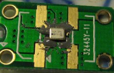
Here are some (crummy, cell phone) pictures of the process. One of the pads had a big blob on it when I attached a wire, I left it -- there are no extra points given for prettiness here, get the wires securely attached, and leave them that way.

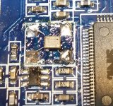
Here is it is installed. This is in a Mini-DSP 2x4HD (a 24.576MHz oscillator).
By The Way -- the pic shows it installed backwards! I took the photo before I realized that and then had to pull the leads up and turn the part around. Forgot to take another picture after that. So if you're doing a 2x4HD, make sure the oscillator is rotated 180degree relative to this photo!

Tack-solder FAST, don't linger on the pads.
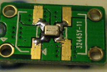
Much of of the goo shown in the second photo is from removing the old oscillator. A trick to doing that is to melt and flow solder on all 4 terminals of the old part. Add enough solder to get more mass to hold heat and help you get good contact with the iron on all pins (don't worry if they short together until you get the part off). Keep moving the soldering iron from pin to pin to get to where all are sufficiently melted loose to release the part (push gently inward when heating the pins, the part will pop away when it is ready). This may not be so good for the part you are removing, so don't count on using it again. Also, if you clean the area with alcohol and an small brush after removing the old oscillator (I didn't) it will look a lot less messy than in that photo!
Adaptor boards would likely make installing the new part easier (and would certainly look nicer), but if you aren't concerned with internal appearance, the fine-wire technique will function just as well.
Here is it is installed. This is in a Mini-DSP 2x4HD (a 24.576MHz oscillator).
By The Way -- the pic shows it installed backwards! I took the photo before I realized that and then had to pull the leads up and turn the part around. Forgot to take another picture after that. So if you're doing a 2x4HD, make sure the oscillator is rotated 180degree relative to this photo!
Tack-solder FAST, don't linger on the pads.
Much of of the goo shown in the second photo is from removing the old oscillator. A trick to doing that is to melt and flow solder on all 4 terminals of the old part. Add enough solder to get more mass to hold heat and help you get good contact with the iron on all pins (don't worry if they short together until you get the part off). Keep moving the soldering iron from pin to pin to get to where all are sufficiently melted loose to release the part (push gently inward when heating the pins, the part will pop away when it is ready). This may not be so good for the part you are removing, so don't count on using it again. Also, if you clean the area with alcohol and an small brush after removing the old oscillator (I didn't) it will look a lot less messy than in that photo!
Adaptor boards would likely make installing the new part easier (and would certainly look nicer), but if you aren't concerned with internal appearance, the fine-wire technique will function just as well.
Attachments
Last edited:
Tks for sharing, i have two more tries..Here are some (crummy, cell phone) pictures of the process. One of the pads had a big blob on it when I attached a wire, I left it -- there are no extra points given for prettiness here, get the wires securely attached, and leave them that way.
Here is it is installed. This is in a Mini-DSP 2x4HD (a 24.576MHz oscillator).
By The Way -- the pic shows it installed backwards! I took the photo before I realized that and then had to pull the leads up and turn the part around. Forgot to take another picture after that. So if you're doing a 2x4HD, make sure the oscillator is rotated 180degree relative to this photo!
Tack-solder FAST, don't linger on the pads.
Much of of the goo shown in the second photo is from removing the old oscillator. A trick to doing that is to melt and flow solder on all 4 terminals of the old part. Add enough solder to get more mass to hold heat and help you get good contact with the iron on all pins (don't worry if they short together until you get the part off). Keep moving the soldering iron from pin to pin to get to where all are sufficiently melted loose to release the part (push gently inward when heating the pins, the part will pop away when it is ready). This may not be so good for the part you are removing, so don't count on using it again. Also, if you clean the area with alcohol and an small brush after removing the old oscillator (I didn't) it will look a lot less messy than in that photo!
Adaptor boards would likely make installing the new part easier (and would certainly look nicer), but if you aren't concerned with internal appearance, the fine-wire technique will function just as well.
I will try again.
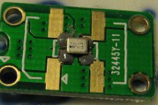
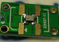
Oscillators arrived today and I have installed them in my IanCanada Dual Clock Board using adapters that I got from Ian.
I used a budget Chinese hot air rework station (cost much less than $100 CAN) to solder them in place, and I followed NDK's heating profile. Before and after pictures attached. I did the 24. Mhz first and that was a bit sloppy with the solder paste. I was neater on the second one.
Not shown is a .1uF decoupling capacitor at V to Gnd on the underside of the adapter board. NDK recommends approximately .01uF so I used .1uF since that was what I had in my spare parts box.
And one warning, I used rubbing alcohol to clean the flux off the board and that took the dots off the oscillators too.
Attachments
Very useful infos, thank you Ben!
As for the 22.5702 MHz and 24.5760 Mhz oscillators, I built two pages on eBay until my own are ready.
Those are available here so you can purchase them directly, if you want:
22.5792 MHz eBay page and
24.5760 MHz eBay page
The actual 4x.xxx MHz GB is still in progress so if there's any interest please express it below:
NZ2520SDA Group buy (for 45.1584 MHz and 49.152 MHz):
1. Lorien - 10 pairs
2. M_Baou - 1 pair
Kind regards,
L
Received, soldered and found working. Thanks!!
//
Have you noticed any sound improvement?
Have you noticed any sound improvement?
This was not a replacement. Sound is good.
//
I replace Chrystek CCHD-957 (45/49 MHz) with NDK NZ2520SDA (22/24 MHz) in my DualXO II ClockBoard from Ian on my Najda DSP I2S input.
I win a better soundstage. More air, better stereo effects, greater depth, beautiful voices.
But i'm subjectively losing bass...
I still have to listen
I win a better soundstage. More air, better stereo effects, greater depth, beautiful voices.
But i'm subjectively losing bass...
I still have to listen
I have a question: is there anyone from the 2x.xxx MHz group Buy who didn't receive his oscillators till now? Last update of that GB was here. I'm tracking all my parcels to be sure that are reaching their destinations but for some it's easier if you'll simply tell me over this thread!
Thank you,
L
Thank you,
L
- Status
- This old topic is closed. If you want to reopen this topic, contact a moderator using the "Report Post" button.
- Home
- Group Buys
- NDK NZ2520SDA oscillators group buy