Hi Shaan
we have briefly mentioned a power supply/supplies. I don't like SMPS as I can't repair them, so they will be linear in my amplifiers. Do I need boutique components, like Schottky diodes, polyprop bypass caps etc.?
I am using two dual power supplies per board, one for just the FETs, and one for the rest, split at the diodes (D1/2). I am adding more capacitance for the FETs, total 22,400uF per rail, just 8,800 for the rest. I do hope this will be enough.
Do you have any idea of output impedance of these amplifiers (V4)?
Hi Shaan
we have briefly mentioned a power supply/supplies. I don't like SMPS as I can't repair them, so they will be linear in my amplifiers. Do I need boutique components, like Schottky diodes, polyprop bypass caps etc.?
I am using two dual power supplies per board, one for just the FETs, and one for the rest, split at the diodes (D1/2). I am adding more capacitance for the FETs, total 22,400uF per rail, just 8,800 for the rest. I do hope this will be enough.
Do you have any idea of output impedance of these amplifiers (V4)?
Hi CS.
If you are talking about the new PSU with speaker protection then No, there will not be a single boutique component on it. You will need a pair of small non-polar electrolytics, however.
Capacitance values seem quite adequate. Take care of grounding.
I have not measured output impedance of V4. Rough guess, it would be close to 20-30milliohm (or less) across the audio band. There has been a case where a member's speakers didn't like the V4 for too low output impedance. A pair of 0.1R 5W resistors at output, and now they do.
")
There has been a case where a member's speakers didn't like the V4 for too low output impedance. A pair of 0.1R 5W resistors at output, and now they do.
Sorry Shaan, did not understand this part
Sorry Shaan, did not understand this part
Some sensitive light-coned drivers installed in some specific type of enclosures do not like (and usually do not need) aggressive cone control which V4 tries to apply by its very high damping factor. The result of which is usually a dry/clinical sound. The 0.1R resistor placed between amplifier output and speaker defeats the damping factor and the cone gets some freedom and the sonics come to life with warmth.
PeeCeeBee V4H First Tests
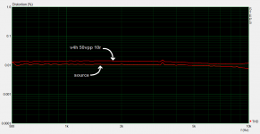
So, here is a THD sweep of V4H from 500Hz to 10KHz taken at 50VPP output into 10R load (32Watt RMS). +/-35V PSU. Total 100mA output bias. 10mA VAS bias. No Zobel. BC5xxB input + KSE3xx vas + 2SK/J output.
Lower curve - Source THD (-10dB line-in magnitude)
Upper curve - V4H THD (-10dB line-in magnitude)
Comparing the two curves we get
THD1Khz - 0.003%
THD2Khz - 0.003%
THD3Khz - 0.003%
THD4Khz - 0.002%
THD5Khz - 0.002%
THD6Khz - 0.0015%
THD7Khz - 0.0015%
THD8Khz - 0.002%
THD9Khz - 0.0025%
THD10Khz - 0.003%
Note that instead of the gradually rising THD vs frequency of V4 we now have a nearly steady THD which actually gradually decreases somewhat as frequency increases.
Good/Bad?
More tuning ahead. So far V4H has shown much better high frequency THD than V4. Let's see how much further it can go without getting more complex, without using a buffer for MOSFETs, without changing the feedback network resistor values and without using high-end components.
So...more coming soon.
Attachments
Last edited:
So, here is a THD sweep of V4H from 500Hz to 10KHz taken at 50VPP output into 10R load (32Watt RMS). +/-35V PSU. Total 100mA output bias. 10mA VAS bias. No Zobel. BC5xxB input + KSE3xx vas + 2SK/J output.
Lower curve - Source THD (-10dB line-in magnitude)
Upper curve - V4H THD (-10dB line-in magnitude)
Comparing the two curves we get
THD1Khz - 0.003%
THD2Khz - 0.003%
THD3Khz - 0.003%
THD4Khz - 0.002%
THD5Khz - 0.002%
THD6Khz - 0.0015%
THD7Khz - 0.0015%
THD8Khz - 0.002%
THD9Khz - 0.0025%
THD10Khz - 0.003%
Note that instead of the gradually rising THD vs frequency of V4 we now have a nearly steady THD which actually gradually decreases somewhat as frequency increases.
Good/Bad?
More tuning ahead. So far V4H has shown much better high frequency THD than V4. Let's see how much further it can go without getting more complex, without using a buffer for MOSFETs, without changing the feedback network resistor values and without using high-end components.
So...more coming soon.
Very interesting.
can you please share the schematic changes?
Thanks
Very interesting.
can you please share the schematic changes?
Thanks
Yes I will in a new thread. Please hold on until its ready.
Some sensitive light-coned drivers installed in some specific type of enclosures do not like (and usually do not need) aggressive cone control which V4 tries to apply by its very high damping factor. The result of which is usually a dry/clinical sound. The 0.1R resistor placed between amplifier output and speaker defeats the damping factor and the cone gets some freedom and the sonics come to life with warmth.
Damping factor is much more influenced by speaker cable than amplier and speaker itself , damping factor should be calculated from amplier ,cable and speaker as whole .
GB3 Update
arasuk - 2 PCBs - SHIPPED
kpsthakur - 2 PCBs + 2x K1058 + 2x J162 - SHIPPED
RomanM - 2 PCBs - SHIPPED
CitizenKane - 4 PCBs - SHIPPED
loafimus - 2 PCBs - SHIPPED
gtose - 4 PCBs - SHIPPED
yyzz - 4 PCBs + 2x K1058 + 2x J162 - SHIPPED
danielhk - 2 PCBs - SHIPPED
gabbar - 2 PCBs + 4x K1058 - SHIPPED
userguide - 2 PCBs - SHIPPED
pluplog - 2 PCBs + 2x K1058 + 2x J162 - SHIPPED
fredlock - 2 PCBs - SHIPPED
pieter t - 4 PCBs - SHIPPED
finneybear - 2 PCBs + 2x K1058 + 2x J162 - SHIPPED
zebulo - 2 PCBs + 2x K1058 + 2x J162 - SHIPPED
Zero Cool - 2 PCBs - shipping invoice sent
Boards received here in London. Thanks Shaan!
My pleasure.

There have been a week long delay in outbound customs clearing for all the packets I sent abroad. Good to know they're moving.
are the vc4h‘s ready?
Almost. V4H will be ready within a few days, along with V4 Rev2.
Almost. V4H will be ready within a few days, along with V4 Rev2.
V4 Rev 2 ?... I am excited...
Almost. V4H will be ready within a few days, along with V4 Rev2.
Rev 2 ???????????????????
- Home
- Group Buys
- PeeCeeBee V4 GB!