Hi Thimios.
I think it will run fine with those transistors and 47pF.
Too late shaan, no, they are unstable using ksa1381ksc3503.
I have a donation, part of it's is a set of faulty Peeceebee v4 boards.
In my attempt to repair those i had used ksa, ksc.
They oscillate badly.
8v on 47R vas load resistor.
Then i swap the ksa, ksc with bd139 140 and everything is fine.
I have some photos from the setup process but i don't know where i must post.
Sorry to be late.
Does increasing 47pF to 56/68pF help?
I don't know.
My first effort is to repair those faulty boards.
Now i think that they are in good condition. Everything looks good.
Next step will be the modified compensation.
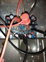
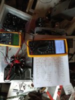
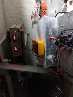
The test setup.
Vas current, mosfet bias, offset voltage measured all together.
Two regulated power supplies used for +/- supply.
Vas current, mosfet bias, offset voltage measured all together.
Two regulated power supplies used for +/- supply.
Attachments
Last edited:
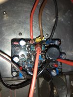
These two boards are a part of a Big very Big donation.
Thanks Man!!!")
The member who donated,gave those as faulty.
During repair i didn't seen any wrong placed part,not something like short circuit not dry soldering.All looks good,very good job.
I believe that he failed during setup procedure.
I will post, as built shematic and measurements soon.
I will try to post the trimmer setup procedure with pictures to help others not fail again.
Thanks Man!!!
The member who donated,gave those as faulty.
During repair i didn't seen any wrong placed part,not something like short circuit not dry soldering.All looks good,very good job.
I believe that he failed during setup procedure.
I will post, as built shematic and measurements soon.
I will try to post the trimmer setup procedure with pictures to help others not fail again.
Need some advice: a week or so back the protection relay of the left channel of my V4 kept cutting off the speaker output. I'm using Shaan's PSU. I checked the DC offsets on both left and right channels and the left had some +19.x mV which gradually increased to about +40 mV. The right was fine (within +/- 1 mV). I adjusted the left channel using VR1 and VR2 pots four days ago to within +/-2 mV.
I just heard the relay click for the left channel. It temporarily cut off the output to the left speaker.
The measured DC offset has increased to 25.x mV in four days.
Any pointers what could be causing the DC offset to increase?
I just heard the relay click for the left channel. It temporarily cut off the output to the left speaker.
The measured DC offset has increased to 25.x mV in four days.
Any pointers what could be causing the DC offset to increase?
What voltage do you measure at the rails?
+35.2 and -35.3V.
Is the offset problem happening with the preamp connected to the amp or the bare amp? If there is dc at preamp's output then it will get to amp's output.
If preamp output has zero DC then please check whether the four 47ohm resistors near the output are warm when the offset is high. This will indicate if the amp is oscillating or not.
If preamp output has zero DC then please check whether the four 47ohm resistors near the output are warm when the offset is high. This will indicate if the amp is oscillating or not.
Is the offset problem happening with the preamp connected to the amp or the bare amp? If there is dc at preamp's output then it will get to amp's output.
If preamp output has zero DC then please check whether the four 47ohm resistors near the output are warm when the offset is high. This will indicate if the amp is oscillating or not.
The high offset is observed when the amp is disconnected and checked on the bench without any preamp connected. The same high offset is seen even when measured with speakers connected (without playing music).
I have checked DC offsets for the entire chain. CD player has zero (I guess it must be having a DC blocking capacitor). My buffer (Kuartlotron) is DC coupled. I checked the offset when I started facing this issue and it was within +/-2 mV. That's when I checked the offset for both channels of PeeCeeBee V4 and observed ~+40 mV on one channel, while the other was fine.
I will check the 47R resistors. This evening I adjusted VR1 and 2 again and monitored the offset for about an hour. I had adjusted to about 0.5 mV but it increased to about 4 mV. I zeroed it again, then started playing music.
I also reflowed VR1 and 2 and some of the components close to these trimpots because I find VR1 has a hair-trigger response and can sometimes increase/decrease rapidly while adjusting.
I will continue to monitor. I was also thinking of swapping out the 500R trimpots to fresh ones in case either of these are unstable.
Hi Shaan,
47Rs are hot after the amp is kept on for about 30 mins. I could not touch it for long. The 47Rs on the other, normal channel are also hot, but not as hot. I could touch them longer. Are these zobel resistors supposed to be hot at all?
The measured DC offset after about 30 mins was around 28 mV (it was initially zeroed then kept on without playing music).
C7, C9 mods are done on my boards.
Kindly advise what else I should check. Thanks, as always.
The problem channel is probably oscillating. Did you replace VR1 and 2?
Please check continuity between PSU ground and heatsink metal. Also check whether all ground connections are tight. Check the solder joints of C1, C9, C10.
If all seems normal but the problem still persists, please unscrew the module and ship it to me. I will check it out myself.
Please check continuity between PSU ground and heatsink metal. Also check whether all ground connections are tight. Check the solder joints of C1, C9, C10.
If all seems normal but the problem still persists, please unscrew the module and ship it to me. I will check it out myself.
The problem channel is probably oscillating. Did you replace VR1 and 2?
Please check continuity between PSU ground and heatsink metal. Also check whether all ground connections are tight. Check the solder joints of C1, C9, C10.
If all seems normal but the problem still persists, please unscrew the module and ship it to me. I will check it out myself.
VR1 and 2 not yet replaced but I do have spare trimpots. I will replace tomorrow.
I did check continuity from PSU ground to heat sink and both channels showed continuity.
I will check ground connections and solders of C1, 9, 10.
Just to put a closure to the problems described above, the suggested changes and checks on the v4 amp board were done and the result was the offset was better after adjustment, but it tended to go up gradually to 15-18 mV. I adjusted a few times but it invariably climbed back to about 18 mV. Since the protection relay stopped randomly clicking and seemed to be stable, I ignored the offset value and had been listening that way with no ill effects.
However, lately, the relay started misbehaving again, sometimes refusing to switch on immediately, but it usually switched on its own later. Till one fine day it completely refused to switch on. I checked the amp board again for offset and it was still stable at about 18 mV (max). So I deduced that it wasn't the amp board that was shutting down the protection switch. So I reflowed all solder points on the offending channel and all is good now. So there was a dodgy contact in there somewhere.
Thanks for all the guidances.

hello Shaan
I'm about to get around to constructing the boards, at last. I have all the components to make two stereo pairs (4 in all), and I'm going to split the output FET's power supply (+/- 35v) and the rest (+/- 42 volts).
What I would like to know is about the resistors. I have boutique capacitors for the main boards, but just high precision metal film resistors for the construction. In your experience, do boutique resistors make all that difference?
thank you.
hello Shaan
I'm about to get around to constructing the boards, at last. I have all the components to make two stereo pairs (4 in all), and I'm going to split the output FET's power supply (+/- 35v) and the rest (+/- 42 volts).
What I would like to know is about the resistors. I have boutique capacitors for the main boards, but just high precision metal film resistors for the construction. In your experience, do boutique resistors make all that difference?
thank you.
In some amps precision resistors do make a difference. Not much difference to expect in this amp unfortunately, or probably fortunately.
- Home
- Group Buys
- PeeCeeBee V4 GB!