yes. i pot all sun now!
thanks
I want to know how much costs I / V (pure vacuum tube) with the power supply and how to do it to order it.
Thanks
Hi. Quanghao makes great kit, but sometime getting all the info is kind searching on Tresor Island ")
Here my own version of the Part Lists to build this DAC with the Tube IV and HV supply.
May be usefull to others, take note that prices are in $CAN...
Here my own version of the Part Lists to build this DAC with the Tube IV and HV supply.
May be usefull to others, take note that prices are in $CAN...
Attachments
Hi. Quanghao makes great kit, but sometime getting all the info is kind searching on Tresor Island
Here my own version of the Part Lists to build this DAC with the Tube IV and HV supply.
May be usefull to others, take note that prices are in $CAN...
Like, thanks
I want to know how much costs I / V (pure vacuum tube) with the power supply and how to do it to order it.
Thanks
Ok, i can open GR for IV, thanks
quanghao
Hi. Quanghao. I received my dac kit in perfect condition. Thanks
Three (3) questions:
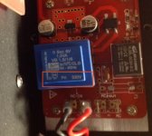
1) The front control PCB has a 6V transformer, but the primary seems to be 230V ONLY, not 115/230V. Also the DAC rear panel indicates only 230V. Is that mean that I cannot use the dac at 115V (in North America) and I need to replace the controller transformer?
2) Tube IV Mute: Where do I connect it on the front controller PCB?
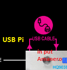
3) ES9038DAC USB Power Dip switch. What is the setting of this switch of I want to supply the Amanero with the DAC supply? I guess I have also to modifiy the Amanero PCB as well?
Thanks
SB
Three (3) questions:
1) The front control PCB has a 6V transformer, but the primary seems to be 230V ONLY, not 115/230V. Also the DAC rear panel indicates only 230V. Is that mean that I cannot use the dac at 115V (in North America) and I need to replace the controller transformer?
2) Tube IV Mute: Where do I connect it on the front controller PCB?
3) ES9038DAC USB Power Dip switch. What is the setting of this switch of I want to supply the Amanero with the DAC supply? I guess I have also to modifiy the Amanero PCB as well?
Thanks
SB
Attachments
Three (3) questions:
1) The front control PCB has a 6V transformer, but the primary seems to be 230V ONLY, not 115/230V. Also the DAC rear panel indicates only 230V. Is that mean that I cannot use the dac at 115V (in North America) and I need to replace the controller transformer?
YES
2) Tube IV Mute: Where do I connect it on the front controller PCB?
To J4 on LCD
3) ES9038DAC USB Power Dip switch. What is the setting of this switch of I want to supply the Amanero with the DAC supply? I guess I have also to modifiy the Amanero PCB as well?
Yes, 3.3V from DAC, but need remove 3.3V from Computer, with cut in Amanero
Thanks
quanghao
You miss this one
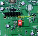
Q1: ES9038DAC USB Power Dip switch. What is the setting of this switch of I want to supply the Amanero with the DAC supply, see image?
And this new one:
Q2: If I use the Raspberry Pi-3 server, how do I connect the Rasp Pi-2 to the DAC?
Thanks
SB
Q1: ES9038DAC USB Power Dip switch. What is the setting of this switch of I want to supply the Amanero with the DAC supply, see image?
And this new one:
Q2: If I use the Raspberry Pi-3 server, how do I connect the Rasp Pi-2 to the DAC?
Thanks
SB
Attachments
Last edited:
Great. Thanks
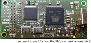
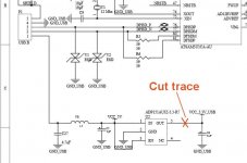
BTW found the info on the ES9018 Dac thread on how to mod the Amanero to use the DAC supply instead of the USB 5V. There is just one trace to cut, or one ic to remove, see image... Never tried it myself yet.
From the thread:
Two points:
- the Amanero board must be modified to disable the incoming USB 5V power, see extract from the Amanero schematic
- 3.3V USB supply on the DAC-END-R must be enabled with the DAC PCB DIP switch
SB
Attachments
Last edited:
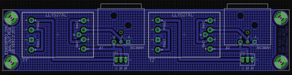
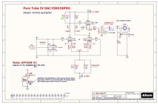
Tested Pure IV tube stage today, and it is a great PCB. I updated the schematics with the exact Part ID, and also added the PCB parts that are not used. Also tested the CCS that can replace R*1/R*3 and was shown on some previous posts. The original values were probably incorrect. I got good result with RK1 330R, and the current adjust RCS1 at about 1K8, for a CCS current of around 1ma. This resistor R*1/R*3 adjust the circuit gain, so the CCS current do the same. With the stock 22K value, the gain is 14dB, with the 1ma CCS it is 20dB. The rest of the specs are the same except the Zout of 560R (if using R4/R22), or a higher 2K2 with the 1ma CCS. Also the THD is slightly lower with the CCS at 0.02%, compare to 0.07% with the resistor. See the complete measurement results tested (tested with a 50R generator accross the two input 27R resistors):
Noise (inputs gnd): 0.5mV
(R*1 =22K)
Sensitivity: Vin: 140mV for Vout: 1V, Gain 14dB
Zout: 560R (R4 is installed with a 560R)
BW: 1.5Hz to 550Khz (2u2F output cap)
THD: 0.07%
(R*1 =CCS, 1ma)
Sensitivity: Vin: 100mV for Vout: 1V, Gain 20dB
Zout: 2K2
BW: 1.5Hz to 426Khz
THD: 0.02%
I cannot listen to either version with 22K or the active CCS, but I modified the board to install a selection jumper to use either the CCS or the resistor. Once the DAC is completed I'll make up my mind. Now time to test the HV regulator pcb
Attachments
Last edited:
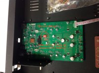
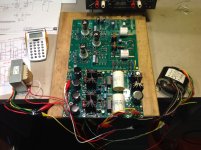
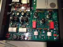
HV Power supply is working like a charm the first time, very nice circuit. I had just to adjust a little the first drop resistors (CRC filter) to adjust for my transformer secondary voltages. The regulator voltage trimmer are also working perfectly. I'll post some volt readings tomorrow. In the mean time here the prototype with the actual load, the Pure IV stage
Attachments
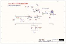
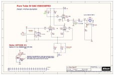
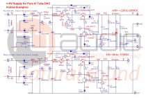
Here the schematic with reference volt/current readings. I'm not using HQ Audio HV/FIL transformer, but rather two transformers I had in stock, and I had to re-adjust R16 from 470R to 1K5. Your millage may vary depending on the transformers you use. Mine are compatible 115/230V. You can see that the regs are doing a very good job at keeping the noise very low, the max ripple is on the +220V at a very low 0.5mv. I also added a small heatsink on Q4...
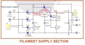
The HV/FIL transfo is R26-90, availabel from ebay. The FIL secondaries are too low at 9V, but I use them in parallel and since I'm running the primary at 120V, instead of 115V, I have 13.4Vdc before the LDO LT1085C regulator I'm using. This IC is usuable as low as 1V differential, so I'm just ok for 12V FIL. It is working just fine, I can adjust 12V, and the ripple is a very low 0.1Mvac)
The -100V supply transfo is done using a volt isolation transfo (115/230 to 115V) from Triad, available from Mouser, the 553-N68X
Attachments
Last edited:
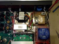
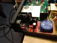
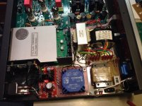
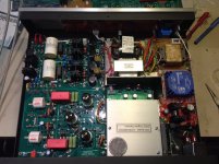
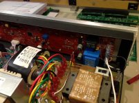
Finally the DAC is signing Here the pictures. I had to make a lot of mods on the inside to install the needed power transformers 115/230V compatible, and have provision for this primary voltage selection. I had one transformer for B+/FIL (T1), one for B- (T2), one for the DAC (T3) and finally one for the High current discrete 5V supply for the Raspberry Pi3 (T4). The Raspberry trasnfo PCB has the necessary AC primary voltage distribution and 115/230V selection switch for T1 & T2. I used a nice pcb from HQ Audio for the Rasberry 5V regulator. It uses the LT3042 High current low noise smd IC, with an D45H11 current booster. Worked like a charm
I had also to replace the front controller 230V transformer by an other one with 115/230V primary. Simple junction points allow voltage selection for this one.
I installed a shield over the DAC PCB, and the I/V current outputs go through feedthrough. An extra shield separates the DAC from the AC transformers. Don't know if it was necessary but it was easier to plan them right from the start, then to add them later. I also installed an AC Inlet module with EMI filter/switch and built-in fuse to replace the standard inlet.
The DAC is completely silent, except for a small hiss at max volume, typical tube thermal hiss probably. But it is very low and not in the way of the music.
Listening to it using the Amanero USB interface (modified to use the DAC digital supply, not the USB +5V) and JRiver. Sound is incredible with DSD output, and very nice choice of digital filter by the way, still haven't had the time to compare all of them.
Pure I/V PCB has MK132 27R current conversion resistor, Kiwame cathode resistors, Active CCS option on the output tube cathode, large MKP Wima local B+/B- filter caps (an addition I did) and Mundorf MCap EVO output coupling caps. Also the output section is already modified to accept an optional balanced output, using Lundhall Transformers.
Next thing I may try are active CCS on the tube anode, to replace the passive 33K resistors. But so far it is a great DAC
And naturally I still have to configure/try the built-in Moode Raspberry music server...
Here the pictures. I had to make a lot of mods on the inside to install the needed power transformers 115/230V compatible, and have provision for this primary voltage selection. I had one transformer for B+/FIL (T1), one for B- (T2), one for the DAC (T3) and finally one for the High current discrete 5V supply for the Raspberry Pi3 (T4). The Raspberry trasnfo PCB has the necessary AC primary voltage distribution and 115/230V selection switch for T1 & T2. I used a nice pcb from HQ Audio for the Rasberry 5V regulator. It uses the LT3042 High current low noise smd IC, with an D45H11 current booster. Worked like a charm I had also to replace the front controller 230V transformer by an other one with 115/230V primary. Simple junction points allow voltage selection for this one.
I installed a shield over the DAC PCB, and the I/V current outputs go through feedthrough. An extra shield separates the DAC from the AC transformers. Don't know if it was necessary but it was easier to plan them right from the start, then to add them later. I also installed an AC Inlet module with EMI filter/switch and built-in fuse to replace the standard inlet.
The DAC is completely silent, except for a small hiss at max volume, typical tube thermal hiss probably. But it is very low and not in the way of the music.
Listening to it using the Amanero USB interface (modified to use the DAC digital supply, not the USB +5V) and JRiver. Sound is incredible with DSD output, and very nice choice of digital filter by the way, still haven't had the time to compare all of them.
Pure I/V PCB has MK132 27R current conversion resistor, Kiwame cathode resistors, Active CCS option on the output tube cathode, large MKP Wima local B+/B- filter caps (an addition I did) and Mundorf MCap EVO output coupling caps. Also the output section is already modified to accept an optional balanced output, using Lundhall Transformers.
Next thing I may try are active CCS on the tube anode, to replace the passive 33K resistors. But so far it is a great DAC
And naturally I still have to configure/try the built-in Moode Raspberry music server...
Attachments
Last edited:
- Home
- Group Buys
- DAC ES9038 PRO GR 2