I mistakenly thought the parts I had were thin film, when in fact they were thick film.
yup.
what are ideal electrolytic alternatives for the 100uF spot on the capmx?
there's a worldwide smd cap shortage and i don't think i even see any x7r 25V 47uF or higher MLCCs on digikey or lcsc.
i'm currently using a 100uf rubycon yxg, but not sure if there's something better suited.
Last edited by a moderator:
Alright, some more questions about the resistors - the revised values specifically.
In the original low impedence BOM, R6 is 47R.
The first time you mention your revised low impedance resistor network it is 1R:
Some posts later you describe it again in a reply to someone but mention only R3 through R5, and leave out R6.
What's R6 in the revised network?
In the original low impedence BOM, R6 is 47R.
The first time you mention your revised low impedance resistor network it is 1R:
R3 = 820R
R4 = 47R
R5 = 220R
R6 = 1R
Some posts later you describe it again in a reply to someone but mention only R3 through R5, and leave out R6.
R3=820R, R4=33R, R5=220R
What's R6 in the revised network?
R6 is the so-called gate stopper that is there to absorb any oscillations in the gate of the MOSFETs. It could be 0R, but I would leave it at 47R to be safe. I don't know what I was thinking if I ever suggested using 1R. Maybe 10R lowest. But my recommendation is leave at 47R.
R3 should be about 1k or 1k1 - adjust it to get the correct voltage at the source (pin 3) of the MOSFET. The best value is 1/2 of Vcc, but adjusting it too much also changes the bias through the JFET. If you are within 0.5v of 1/2Vcc, leave it alone.
R4 adjusts the relative H2 to H3 distortion (larger R4 will be greater H3 but lower overrall THD), but be careful as it also changes bias current - higher R4 is higher bias current. One of the most effective ways to decrease THD and keep a good H2/H3 profile is to use a voltage regulated DC step up for the power supply and adjust so that Vcc is about 18.2v. If you monitor the FFT in real time as you adjust, you will see the optimum place to be. Ideally R4 is somewhere between 33R to 52R, typically, even 39R could be a sweet spot.
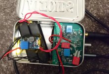
had another fiddle with this today - got it running off two series 14500 Li-Ion cells. Plan is to use 18350 instead (easier to fir spacewise) but having difficulty finding a battery holder for that size...
Also waiting on my order of tp4046 boards to be able to charge them while in the tin.
Also waiting on my order of tp4046 boards to be able to charge them while in the tin.
Attachments
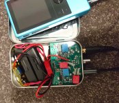
I just didn't want to muck about with the Lipo in the end, and I have a lot of these cylindrical Liion batteries around. Having said that lipo can't be beat for capacity to size though.
I'm getting 2x 840mah with this setup, 18350 would bump it to 2x 900, still only about half what you've got. Draw is ~650ma with step up @ 19v..so about 3 hours of play time optimistically
I'm getting 2x 840mah with this setup, 18350 would bump it to 2x 900, still only about half what you've got. Draw is ~650ma with step up @ 19v..so about 3 hours of play time optimistically
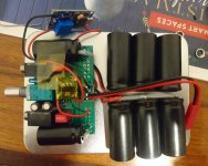
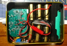
Long overdue build - 18650 build to fit in the oversized tins I got. 3x1000uF KZ & 1uF wima on outputs. I picked the higher current bf862 and 4306s however still only running at 57mA ... When testing I was getting almost 70... Will have to get a few higher value resistors to bump it up.
Also using USB power it bypasses the switch due to how I wired it. Could add in a 4046 to solve it but I don't forsee myself charging it via USB... Probably more of an at home amp which can be easily moved around.
Also using USB power it bypasses the switch due to how I wired it. Could add in a 4046 to solve it but I don't forsee myself charging it via USB... Probably more of an at home amp which can be easily moved around.
Attachments
Last edited:
What would be the easiest way to desolder the jfet?
If you have a pencil tip hot air gun, aim nozzle set to 275C for about 10-15 seconds and it should loosen up.
With a soldering iron, add extra solder to each joint and heat them up in succession until all molten and pick off with tweezers. Use copper braid to clean off excess solder. Then resolder with one pin first while holding body down with tip of tweezers.
Just had a go with that - I swapped it with one i got from rs components (which measured at a lower current) but once in circuit it gives a higher bias than the reading I got while matching them would suggest, higher than the Aliexpress ones. Aliexpress fake jfet? Not too sure but something is definitely up. Probably gonna order some more from rs
I ordered some BF862’s from eBay and I’m not sure about them. They may have substituted a different/cheaper sot23 package device. The case code on the devices I have is MTW, 61. I can’t find any device that matches that case code so I’m hesitant to use these in any build.
That marking code sounds suspicious. Mine have always been 2AW, and a code lookup shows that BF862 generally has 2A...
Doscussion here:
Bf862 purchased on ebay - labeled as 2AW2?
BF862 - Model Search - Marking Codes
Doscussion here:
Bf862 purchased on ebay - labeled as 2AW2?
BF862 - Model Search - Marking Codes
- Home
- Group Buys
- xrk971 Pocket Class A Headamp GB