I decided I want to try this amp with my 13 ohm, 115db IEMs. Obviously very sensitive, so hiss is a concern. I can make this a desktop version if I need to.
Wondering if I need to do anything special with this in mind?
I have 10uf input and 2200uf output caps.
Installed 33ohm for r4, but I have a bunch of values from 33 to 68 ohms so I can easily change this.
My original plan was to build with the raptor lightning boards, but I haven't actually ordered his pcb's or the parts for them yey.
Thanks
Randy
You won’t have any hiss with 115dB IEMs even. This amp is silent when inputs are zero. Check by grounding inputs. If you hear hiss, it’s your source’s opamp noise.
OK, thanks
I was wondering about the "low impedance" configuration you posted, but I guess that version is for harder to drive cans like planars.
I'm going to start off using a dell laptop PS into a rcrcrcrc filter, and see how that sounds. Going to aim for 17V into the amp.
Randy
Remember to put R across the +ve as well as GND path between the C’s on CRCRC.
I saw that comment earlier in this thread, but I didn't think I saw the ground R's in the pics of your CRCRC filters.
Did I just not look close enough?
I also plan to bypass the lytics with around 0.01uf caps.
Randy
Howdy X, et al ~
Please excuse any rambling, and my many questions
I'm planning a desktop build with irf610's, and am sorting out parts now. I have a regulator on the way(1). I've built a CRCRCRC from 2200uF Panasonic FC caps and 0.47Ohm Fukushima MPC71 5w resistors.
I have 300 or so BF862's, so I'll be measuring and finding a good pair from that. I have irf610's on hand, should I match them as well?
For R7 I've set aside 8x 221 Ohm(measured 220, fwiw) 1/2w RN60D non-inductive metal film resistors. I can do 4 in parallel for ~55 Ohm, or 3, for ~73.333 Ohm.
I have a bunch of different caps, Panasonic sep's, muse, silmic IIs, Nichicon KAs, and dozens of different film caps. I'll sort through them and put together some ideas, combinations, etc.
Besides R7, what else needs to change?
I have a few dc boost boards from ebay if I need to boost the voltage before the CRCRCRC. What's the ideal range for this type of build?
I am going to put it all into a case, no restriction on size as it will sit on my desk next to my dac. I'll build a case, or maybe buy one from ebay, for now I'll attach it to a piece of plywood or something.
Thanks!
Gable
1 - Ultra-low Noise <40μV Adjustable Voltage Regulator Module, Based on LT1963. | eBay
Attachments
Hi Pcgab,
Great to see you starting this project! Look here for the values of resistors that need to be tweaked. There is R3 and R4/5 changes too.
http://www.diyaudio.com/forums/group-buys/302859-xrk971-pocket-class-headamp-gb-38.html#post5014544
For the CRCRC I found that putting R’s on the GND path helps prevent any AC noise from leaking in through the DC step up GND. You don’t need such big resistors. Just 1W can work.
You will need a cap multiplier between your DC step up and CRCRC otherwise the DC goes into auto protect upon power on. Cap Mx reduces ripple but most importantly provides graceful turn on and off to avoid absolutely any thump. Amp is silent even with high sensitivity IEMs upon turn on. There is no danger of an errant pop as with delay and timer circuits which can be tricked if you click on off too fast.
Good luck!
Bias at 110mA or 120ma is good place to be and voltage between 18v and 20v (depending on how good your sinks are). Good to match BF862’s to keep channel balance the same. Match Vgs of IRFs as well.
Last edited:
Nice review of sound of different caps here.
Humble Homemade Hifi - Cap Test
Max Headroom (Dan) gave me that link from my Aksa Lender HPA thread. I am using an “Audiophiler” cap and it actually scored well considering the low price.
Aksa Lender HPA
Humble Homemade Hifi - Cap Test
Max Headroom (Dan) gave me that link from my Aksa Lender HPA thread. I am using an “Audiophiler” cap and it actually scored well considering the low price.
Aksa Lender HPA
Last edited:
Hi Pcgab,
Great to see you starting this project! Look here for the values of resistors that need to be tweaked. There is R3 and R4/5 changes too.
http://www.diyaudio.com/forums/group-buys/302859-xrk971-pocket-class-headamp-gb-38.html#post5014544
For the CRCRC I found that putting R’s on the GND path helps prevent any AC noise from leaking in through the DC step up GND. You don’t need such big resistors. Just 1W can work.
You will need a cap multiplier between your DC step up and CRCRC otherwise the DC goes into auto protect upon power on. Cap Mx reduces ripple but most importantly provides graceful turn on and off to avoid absolutely any thump. Amp is silent even with high sensitivity IEMs upon turn on. There is no danger of an errant pop as with delay and timer circuits which can be tricked if you click on off too fast.
Good luck!
Bias at 110mA or 120ma is good place to be and voltage between 18v and 20v (depending on how good your sinks are). Good to match BF862’s to keep channel balance the same. Match Vgs of IRFs as well.
Awesome, thank you for the tips X!
I'll see if I have the right bits on hand to make a cap mx, I just ordered some of the cap mx boards that raptor was kind enough to post.
I used the mpc71's because I had them lying around, I may have something more appropriate in the stash if I dig deeper.
Will re-do rcrcrcrcrcrcrcrcrc(however many letters it is...) with the r's on negative side.
Will match the irf's as best I can, I think I only ordered 10 or so.
Thanks again for the pointers, and thank you Raptor for the cap mx board design gerbers.
Review on Head-Fi
Member Brooko on Head-Fi just completed a review of my NHB amp. He loves the sound of course. Although I gave him the amp as a free sample to keep, he likes it so much he wants to buy it
XRK Audio NHB Portable Class A | Reviews | Head-Fi.org

Member Brooko on Head-Fi just completed a review of my NHB amp. He loves the sound of course. Although I gave him the amp as a free sample to keep, he likes it so much he wants to buy it
XRK Audio NHB Portable Class A | Reviews | Head-Fi.org
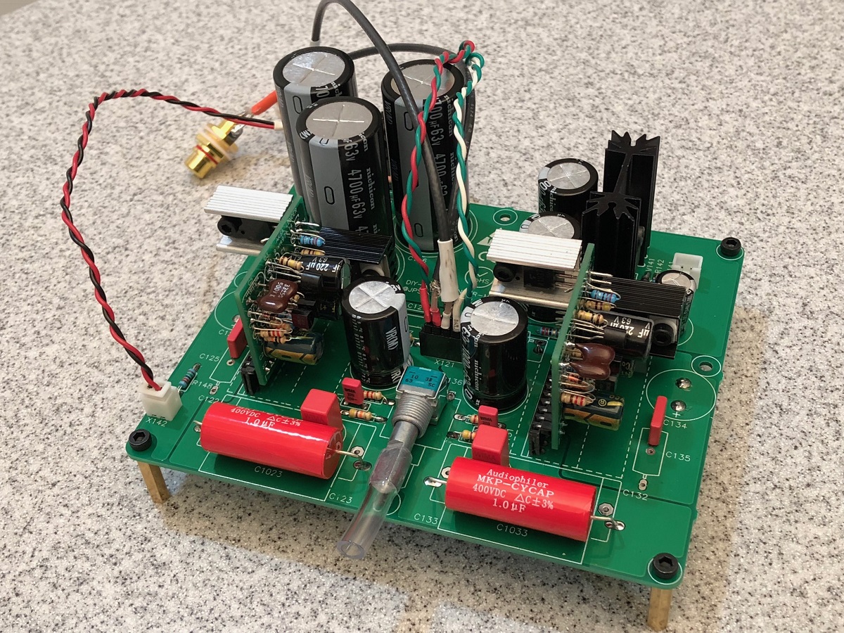
Fired up my build last night.
For power, I'm using an old Dell Laptop adapter (19.5V out), cut off the connector and wired into my rc x 4 filter.
First r is 15 ohms, all other r's are one ohm. I also added a 300 ohm load resistor across the last cap, to put a little more load on it.
Using mostly the "standard" parts list, I think I substituted a film sm cap in there. Using 33 ohm for r4.
Output caps are a pair of 1000 uf oscons per channel (2000uf total per ch), input is a 10uf silmic. No bypasses right now.
Bias is 56 ma, input voltage a little over 16V.
EDIT: I'm going to try changing the first R to 10 ohms to get around 17V in.
I measured the transistor temps but forgot what it was. Maybe 130F or so?
plan to get some little heatsinks.
Sounded pretty good, but I'm letting it run in today to burn in the caps.
Wondering if I can lower the gain? With my sensitive IEM's, its' kind of hard to adjust the pot because a little movement makes a large volume change. Also, with the pot I have, there is some channel imbalance at very low volume levels.
Randy
Last edited:
Wondering if I can lower the gain? With my sensitive IEM's, its' kind of hard to adjust the pot because a little movement makes a large volume change. Also, with the pot I have, there is some channel imbalance at very low volume levels.
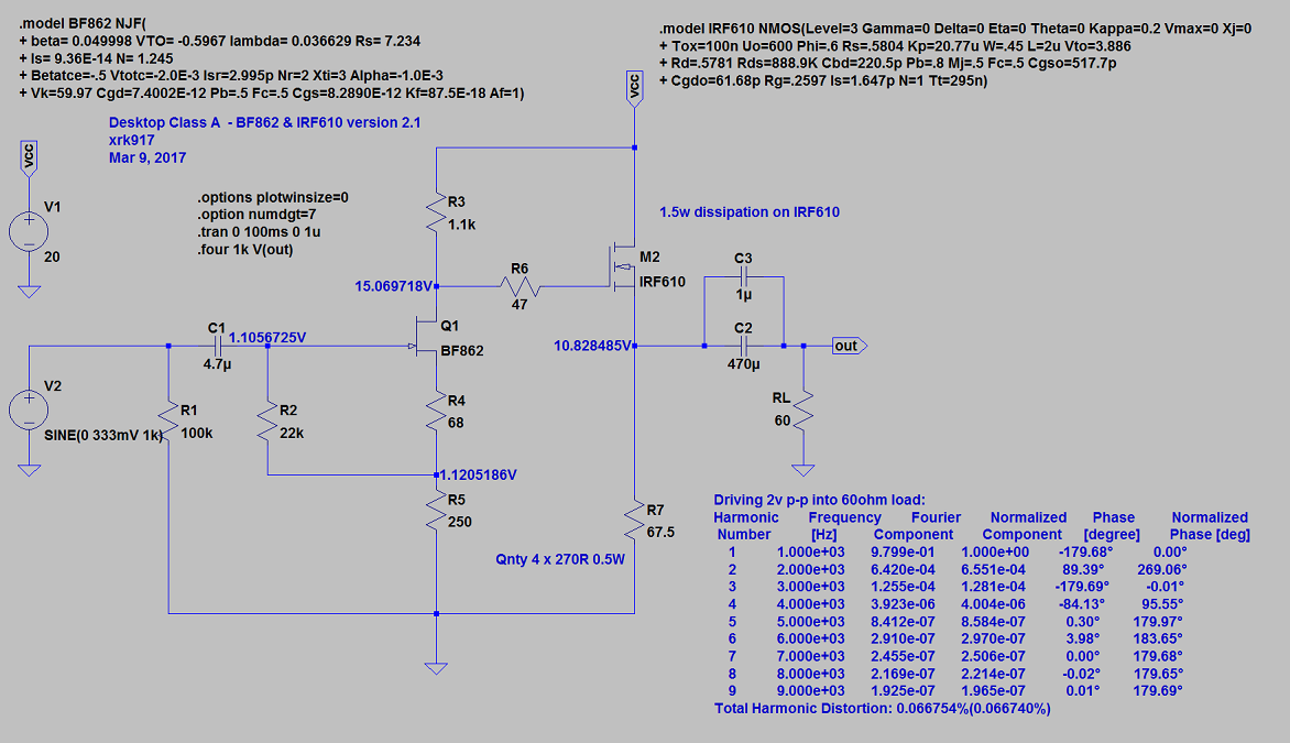
The channel imbalance may be due to not using matched FETs (did you match them?). The gain is about 3x and tied to overall resistor network which also sets bias. I have not heard anyone complain that gain is too much.
A simple way to match is to use the actual circuit and measure the voltage across R3 as you press different JFETs onto the pads with the eraser tip from a pencil. This is an in-situ measurement and if you can get the voltage reading to be within 5% it will be pretty good. Once the JFET is in place, put different ZVN4306 MOSFETs on the pads and measure voltage across R7 (bank of 4 x 460R) and try to get that within a 5%. This is a minimal amount of matching and will result in much better channel balance than no matching. If you have lots of FETs you can do better and match to 2%, then 1%, or crazy stuff like I do and match to better than 0.5% like I do for the NHB. It takes a reserve of about 100 FETs to do this effectively though. It is very time consuming to get 0.5% though.
Let me think about an easy way to drop gain for you.
Edit: change R5 to 470R for 1.8x gain (5.2dB) gain and distortion will actually go down too.
That’s an easy change to make.
Last edited:
The channel imbalance may be due to not using matched FETs (did you match them?). The gain is about 3x and tied to overall resistor network which also sets bias. I have not heard anyone complain that gain is too much.
A simple way to match is to use the actual circuit and measure the voltage across R3 as you press different JFETs onto the pads with the eraser tip from a pencil. This is an in-situ measurement and if you can get the voltage reading to be within 5% it will be pretty good. Once the JFET is in place, put different ZVN4306 MOSFETs on the pads and measure voltage across R7 (bank of 4 x 460R) and try to get that within a 5%. This is a minimal amount of matching and will result in much better channel balance than no matching. If you have lots of FETs you can do better and match to 2%, then 1%, or crazy stuff like I do and match to better than 0.5% like I do for the NHB. It takes a reserve of about 100 FETs to do this effectively though. It is very time consuming to get 0.5% though.
Let me think about an easy way to drop gain for you.
Edit: change R5 to 470R for 1.8x gain (5.2dB) gain and distortion will actually go down too.
That’s an easy change to make.
I'm using your uber matched FETs
I also bought at least 10 of each value resistor, and hand measured/matched all resistors.
Should be about as good as you can get for matching.
From what I remember, when measuring the bias voltage, they were within 20 mv, or about 3%. Actually should be better based on using nhb matched fets, I'll check again tonight.
There is a large volume drop in one side when I turn the pot, but only at the beginning. So I'm sure that this is a pot issue, I just got unlucky. But with the lower gain by using a 470ohm resistor, this should go away.
Oh, and I don't have a vol pot knob yet, so its a little harder for me to adjust vol, obviously not helping here.
I'm actually somewhat surprised no one has asked for lower gain before. If you use this as a portable amp, you would be driving high sensitivity cans/iems, and this will be a benefit.
Another option you can offer
Thanks
Randy
The 20mV or 0.02v difference in voltage readings across R7 of 117.5ohms is 17uA difference which is 0.3% variation in bias current between left and right channels based on a bias current of 55mA. So it’s probably your pot that’s causing the imbalance issue. Try swapping out the pot or change the gain to lower value so that you use a larger range of the pot. Let me know how the lower gain mod works.
I've also seen other people talk about channel imbalance and problems with pots at low volumes, I think even more so with these tiny pots.
Changed R5 and it worked well. Gives me more adjustability for my iem's, but still enough gain for my full size headphones. My full size are low impedance 50 ohm, so this configuration may not have enough gain for a high impedance can.
Source is a Soekris dac, will try with my portable and see if enough gain with that.
Before the gain change, bias is 56 ma
after change, bias is 56.7 ma, so minor change.
I remembered to let the circuit temperature stabilize before measuring the bias.
I just built a new amp with special NHB low impedance option. With revised resistor network described earlier (R3=820R, R4=33R, R5=220R) and hot running FETs to get 80mA bias current. So the ultimate test are 32 ohm 93dB orthodynamic planars. I just got myself a set of HE400i’s and am happy to say that they are working very well together. No bass dropout or bass distortion on heavy drum beats, and very articulate highs. Reminds me of an AMT.

- Home
- Group Buys
- xrk971 Pocket Class A Headamp GB