I get on to the surface shipping so slow,but it is cheap and so safe.if we use fast air post,it may take 1~2weeks to arrive.the cost is 10USD for 2PCB boards shipping.
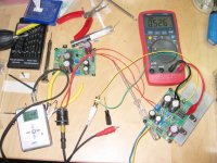
BTW:a Hongkong diyer have finished the boards,and send me some pic show his workshop.
cheers
-digi
BTW:a Hongkong diyer have finished the boards,and send me some pic show his workshop.
cheers
-digi
Attachments
thank you for your appreciation") lately,I have received some e-mails ask for my boards.I may do another round orders.
lately,I have received some e-mails ask for my boards.I may do another round orders.
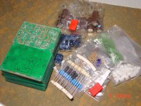
dual mono zen headamp boards,total=60 PCBs (30 sets)
R/C kit,total=10 sets (maybe add,basis on order quantitys)
if you have other ideas,please add comment.
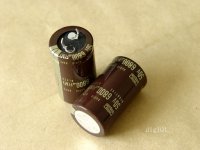
btw:I am considering append power supply caps and bridge diodes in R/C kits.I have find some good components.
such as ELNA standard or Nippon chemi-com 6800u50v caps.
pic view:
lately,I have received some e-mails ask for my boards.I may do another round orders.dual mono zen headamp boards,total=60 PCBs (30 sets)
R/C kit,total=10 sets (maybe add,basis on order quantitys)
if you have other ideas,please add comment.
btw:I am considering append power supply caps and bridge diodes in R/C kits.I have find some good components.
such as ELNA standard or Nippon chemi-com 6800u50v caps.
pic view:
Attachments
The boards is available now.
dual-mono PCB boards, Total = 60 pieces(30 sets)
The price is $3.6 USD per board.building one amp need 2PCBs boards($7.2).the boards including partlist.
surface shipping costs is $5 USD.take 2-6 weeks arrive.
by air ,cost is $10 USD.2 weeks arrive.
R/C kit,total = 10 sets.
each kit can fit 2 dual-mono boards and mono power supply used.
part list-
main boards:
standard film resistors,
R1\R2\R3\R8=1K,1/4W
R4=20K
R5\R6=220 ohm,1/4W
R7=33K,1/4W
R9=220K*,1/4W
R13=100K*,1/4W
R14=180K*,1/4W
R15=470 ohm,1/4W
dale resistors,
R10\R11\R12=1 ohm,1W
R18=5.6 ohm ,3W
C1\C3=100uf/35V ,ELNA CERAFINE
C2=4.7u100vBP (For audio)
C4\C5=1000uf/63v ,ELNA FOR AUDIO
C6=2200uf/50v , ELNA Standard Audio Grade
socket,2 pins output/psu
small socket,input
power supply partlist,(for dual-mono building)
ELNA standard 6800u50v cap*4
1n4001 diode*8
25x40 holes bread board*2
pre R/C kit,the total cost is $40 USD.
surface shipping cost is $5.
by air it is $15.
you need to email me directly to place an order.
My e-mail : vcgft@yahoo dot com dot cn
Attachments
Talk me into it
Digi01,
As you know, I built a Zen headamp recently using perfboard and point to point wiring, but I was well into building it when you made the pcb/kit offering, so I decided against buying some of your boards. I have had my amp completed for a few months now, and I have been slowly tweaking it into better performance, including following a couple of your suggestions. This circuit definitely benefits from some carefully considered tweaks.
Of course, now I can't help but wonder how much benefit is achieved by using a good pcb instead of perfboard, and now that you are offereing pcb's again it has become a factor my curiosity won't let me ignore. You mentioned to me once that my amp circuit looked similar to the first version you built. So ... does the circuit on a PCB sound significantly better than with point to point wiring?
For the record, the changes that I found made the biggest difference in sound quality:
1) Replace the potentiometers with fixed value resistors once you know what exact values you want.
2) Add a film bypass cap to the output electrolytics.
3) A separate P/S voltage regulator circuit for each channel made a whopping difference.
4) More bias (I'm running mine at 0.3A)
If you think the PCB's will make a noticeable difference, then sign me up for a set. Looking forward to your thoughts.
Please notice:
the R/C kit not including dual-mono main amp PCB boards,only 2 bread boards for power supply parts building.
so,the all parts kit (amp boards+R/C kit) cost is $47.2 USD.
and in psu parts,it has a couple of ELNA standard 6800u50v caps for dual mono psu building,but not 4 caps.sorry for my mistakes.
for Brian Donaldson
I am very interest in compare ZEN & alpha.in fact,I am making a minia headamp nowwaiting your test result.
-digi
the R/C kit not including dual-mono main amp PCB boards,only 2 bread boards for power supply parts building.
so,the all parts kit (amp boards+R/C kit) cost is $47.2 USD.
and in psu parts,it has a couple of ELNA standard 6800u50v caps for dual mono psu building,but not 4 caps.sorry for my mistakes.
for Brian Donaldson
I am very interest in compare ZEN & alpha.in fact,I am making a minia headamp now
waiting your test result.-digi
for metalman
thanks for you share your circuit debug course on forums,it is coolI agree with you point,the circuit definitely performances from tweaks.P2P or PCB mounting mode,can all adjust to very good performance.
supplement some improve sound quality modification idaes:
1,match R10 and R12,obtain stability DC work point.
2,use dual mono building, separate common ground.
3,choose top grade components.such as use 100uf/35v BP cap for C3.
4,adjust amp gain setting, you can check out this thread for some detail:http://www.diyaudio.com/forums/showthread.php?s=&threadid=12243&highlight=headphone
5,use battery power.or improve psu voltage,my ZEN run at 35V pre channel 200ma bias.
as Pellerano mentiond,the amplifier is quite sensitive to component quality. Q1 and Q2 are critical.IR or Motorola brand IRF610 is good.2sk214 is another choice,but need testify.
btw,you setting the bias at 0.3A.what headphone are you useing?
regards
-digi
thanks for you share your circuit debug course on forums,it is cool
I agree with you point,the circuit definitely performances from tweaks.P2P or PCB mounting mode,can all adjust to very good performance.supplement some improve sound quality modification idaes:
1,match R10 and R12,obtain stability DC work point.
2,use dual mono building, separate common ground.
3,choose top grade components.such as use 100uf/35v BP cap for C3.
4,adjust amp gain setting, you can check out this thread for some detail:http://www.diyaudio.com/forums/showthread.php?s=&threadid=12243&highlight=headphone
5,use battery power.or improve psu voltage,my ZEN run at 35V pre channel 200ma bias.
as Pellerano mentiond,the amplifier is quite sensitive to component quality. Q1 and Q2 are critical.IR or Motorola brand IRF610 is good.2sk214 is another choice,but need testify.
btw,you setting the bias at 0.3A.what headphone are you useing?
regards
-digi
Digi01,
I am using Grado Labs SR-225 headphones, which have a 32 ohm impedance. I am running 30V and 0.3A bias to optimize the amp power output into my headphones, 1.44W into 32ohms. This works out to 138dB max volume, which means that I should never hear it start clipping.
Thanks for the link on setting the gain. I may have to play around to see how different gain settings affect the sound.
Metalman
ftjandra said:Digi01,
Have you or anyone else compared this amp to a PPA? I have a PPA right now, but am very interested in trying this one out if it is very competitive. Also, do you still have some kits left? Thanks.
--Ferdi
the sound of ZEN is very nature,especially in grado series headphone load.I like use it enjoy the vocal and jazz music,only beautiful
I have 6 kit left now,you may give me a mail order it.
-digi
Brian Donaldson said:I may need a a pair to compair to my CCS miniA HP amp.
Hi Brian,your e-mail host maybe have some problem.please give me a mail


Hello,
I have just started testing my circuit after soldering all the components to Digi01s PCB.
I was aiming for a bias current of 300mA but all i seem to be able to achieve is 192mA (0.58V/3).
Here are some measurements that i took
24.8V supply
V R18 = 1.1
V r2 = 3.5
Q3 (ZTX450) B= 12.1, C = 16.8, E = 11.6
Vbe = 0.54
Q2, G = 5.2, D = 11.6, S = 0.58
Q1, G = 16.7, D = 24.1, S = 12.1
can anyone see if anything is wrong from these values?
Also I tried to set the Id(Q1)/Id(Q2) ratio the way tortello suggests on the Headwize site but cant seem to do it correctly.
Tortello's tutorial says to measure the AC contribution across R10 and R12 whilst applying a 1kHz input.
If i connect my scope probe across R10 with the probe ground at one side of R10 and probe at the other end I dont get a proper reading. If i connect the probe between Q1 source and R10 with the probe ground at ground i get a nice sine wave.
When i connect the probe across R12 I dont get any signal no matter how much i adjust R17.
Is this normal or is there something wrong.
Thanks for any help
Mark
Mark,
Lets tackle the bias issue first. Could you measure and post the voltages across R4, R16, R3 and R10. R4 and R16 will have the biggest affect on the bias current here. It may not be possible to get 300mA bias with them in the circuit. At first glance, your other numbers seem OK, but I'll check a little closer.
In my amp I had to remove them to get the bias up to 300mA, but in that case you have to add an extra capacitor in the bias circuit to maintain stability.
Start by measuring and posting those values and we'll go from there. Just so you know, I've benn pretty busy lately, so I may be a little sluggish in replying promptly.
Terry
- Status
- This old topic is closed. If you want to reopen this topic, contact a moderator using the "Report Post" button.
- Home
- Group Buys
- New MINI ZEN Headphone Amp PCB group order...