I am interesting in these boards and like to know the following:
1. Are these boards compatible with all revisions (1, 2 & 3) of Soekris R2R?
2. As Raspberry Pi is my primary input, is it possible to set I2S-2 as default so that it can be Auto-switchable?
3. Besides the Soekris on-board single-ended output buffer, is it possible to add another single-ended output buffer on muting board?
I am interesting in these boards and like to know the following:
1. Are these boards compatible with all revisions (1, 2 & 3) of Soekris R2R?
2. As Raspberry Pi is my primary input, is it possible to set I2S-2 as default so that it can be Auto-switchable?
3. Besides the Soekris on-board single-ended output buffer, is it possible to add another single-ended output buffer on muting board?
1. Yes. Although with the improved muting circuitry in Rev3 DAM the muting board may not be really necessary, it will still work.
2. Yes, it will require soldering a piece of wire between two switch contacts on the switch board. If you plan to use a software controller instead of the mechanical switch, it can be done in software without hardware mods.
3. The muting board has layout for building a SE-BAL output buffer, and DAM1021 has a SE-BAL buffer onboard. Neither one has provisions for a single-ended buffer. Nothing prevents one from adding a separate single-ended buffer, but it can not be built directly on the muting board.
However, the muting board balanced buffer circuitry has impedance disbalance compensation that the DAM buffer does not have. As a consequence, using only positive side of balanced output as single ended signal, will produce almost no degradation.
Thanks for detailed reply. A few more questions:
1. To set I2S-2 auto-switchable, can you provide more details about soldering a piece of wire between two switch contacts on the switch board (your reply #2)?
2. For "Additional muting board parts for balanced build: 10 EUR" of Pricing, are these parts to be used for building SE-BAL output buffer (your reply #3) and are those listed as "Additional parts for SE to balanced buffers build" in BOM of the muting board?
@oneoclock,
thanks again for the hint, see below.
@awietek,
looks nice, what for a enclosure it is?
Thanks.
It's a cooltek U1 - its a bit too small but I'm trying very hard to fit all inside
")
Thanks for detailed reply. A few more questions:
1. To set I2S-2 auto-switchable, can you provide more details about soldering a piece of wire between two switch contacts on the switch board (your reply #2)?
2. For "Additional muting board parts for balanced build: 10 EUR" of Pricing, are these parts to be used for building SE-BAL output buffer (your reply #3) and are those listed as "Additional parts for SE to balanced buffers build" in BOM of the muting board?
I will add the I2S default setting change details to the input board document in a few days.
The muting board balanced parts kit is listed in the BOM as "Additional parts for fully balanced unbuffered build". These are needed to build a dual-mono setup with two DAM1021.
The parts to build a SE-BAL buffer on the muting board need to be obtained separately, I do not provide those. Normally it will be either a dual mono setup or a SE-BAL buffer, but not both.
I will add the I2S default setting change details to the input board document in a few days.
Thanks! That will be great.
The muting board balanced parts kit is listed in the BOM as "Additional parts for fully balanced unbuffered build". These are needed to build a dual-mono setup with two DAM1021.
The parts to build a SE-BAL buffer on the muting board need to be obtained separately, I do not provide those. Normally it will be either a dual mono setup or a SE-BAL buffer, but not both.
This is what I need. Appreciate if you can provide the BOM and details to build a SE-BAL output buffer to the muting board document as well.
PM has been sent to you for the board kits.
Thanks! That will be great.
This is what I need. Appreciate if you can provide the BOM and details to build a SE-BAL output buffer to the muting board document as well.
PM has been sent to you for the board kits.
The buffer parts are listed in the muting board BOM under the section "Additional parts for SE to balanced buffers build" and the manual has a section "Unbalanced to balanced output buffers". There really is not much to it
I don't have your PM, you may want to recheck that.
Im planning to use "turn on/off" module with remote control that uses GPIOpins 15 and 17 for communication with Raspberry.
How are these pins utilised by the input board? Can I just stack that module on the top of pinouts coming of the input board and use it?
The GPIO mapping table is in the input board manual on page 4.
GPIO 15 is Raspberry serial port RX line, which is connected to DAM TXD pin.
GPIO 17 is connected to the RXD pin of the second DAM in dual-mono balanced build. It is not connected to anything in a single DAM1021 build.
If you need to free those GPIOs, you can remove the RN3 resistor network from the input board, which will disconnect RPI and DAM serial lines (GPIO 14, 15, 17 and 27).
For connecting additional modules, you can install a 2x20 pin header J19 on the input board as shown in the manual in Fig 14. It is a full replica of the RPi connector, but note the position of pin 1. The RPI module will likely end up placed over the input board, so you need to check if it fits.
The buffer parts are listed in the muting board BOM under the section "Additional parts for SE to balanced buffers build" and the manual has a section "Unbalanced to balanced output buffers". There really is not much to it
I don't have your PM, you may want to recheck that.
Just resent my PM. Please check.
OK - so I put stuff together but having a no power coming to the switch - none of the leds is on - including power one.
I have DC power supply connected to the input board (7,8V), RPI is powered by the external module - as you suggested I removed RN3 resistor network from the input board, which disconnects RPI and DAM serial lines (GPIO 14, 15, 17 and 27). I also removed resistor R0 situated next to the power in pins.
LED light on the board is on, both jumpers are on (LED and power), RPI is starting through the module that I stacked on the top of the input board.
The 10pin tape connecting board with switch is connected properly - I even used single pin cables to connect it to exclude any problems with the tape - still no luck.
The light on the DAC is flashing which means that is not locking the sync... Not sure what to do next...
I just got my Input boards and two Soekris Dacs, which I want to assemble with RPI3 to one System, playing directly I2S...
...has anyone this Setup running already ? Which Software are you using on the RPi ? I guess the clock is not fed back into the RPi or is it ? So no Botic ?
...has anyone this Setup running already ? Which Software are you using on the RPi ? I guess the clock is not fed back into the RPi or is it ? So no Botic ?
The parts to build a SE-BAL buffer on the muting board need to be obtained separately, I do not provide those. Normally it will be either a dual mono setup or a SE-BAL buffer, but not both.
For SE-BAL buffer, there are pinouts for R BAL+, R BAL-, L BAL+ and L BAL-, but none for ground. Please advise where the ground should be connected to.
Thanks!
For SE-BAL buffer, there are pinouts for R BAL+, R BAL-, L BAL+ and L BAL-, but none for ground. Please advise where the ground should be connected to.
Thanks!
For balanced connections the cable shield (connector pin 1) should be connected directly to the metal enclosure, not to the signal ground.
OK - so I put stuff together but having a no power coming to the switch - none of the leds is on - including power one.
I have DC power supply connected to the input board (7,8V), RPI is powered by the external module - as you suggested I removed RN3 resistor network from the input board, which disconnects RPI and DAM serial lines (GPIO 14, 15, 17 and 27). I also removed resistor R0 situated next to the power in pins.
LED light on the board is on, both jumpers are on (LED and power), RPI is starting through the module that I stacked on the top of the input board.
The 10pin tape connecting board with switch is connected properly - I even used single pin cables to connect it to exclude any problems with the tape - still no luck.
The light on the DAC is flashing which means that is not locking the sync... Not sure what to do next...
Have you installed the J2 connector (1x10 pin ) on DAM1021 and the input board?
You should also have the EXT POWER and LED ENABLE jumpers installed.
Wow
It's really embarassing - I do apologise for such a rookie mistake... That was missing connector to the dac... I rather listen to good music than solder electronics - but hey, at the end of the day its full success and I'm completely amazed how good this stuff is - dac sounds awesome and this switch/input board is great.
There're still some final touches remaining but right now - thank you Normundus - good job
Attachments
It's really embarassing - I do apologise for such a rookie mistake... That was missing connector to the dac... I rather listen to good music than solder electronics - but hey, at the end of the day its full success and I'm completely amazed how good this stuff is - dac sounds awesome and this switch/input board is great.
There're still some final touches remaining but right now - thank you Normundus - good job
Very cool! I would love to see more photos and learn of the specs of your build.
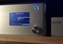
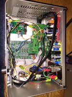
So this is how it looks inside. This is my first ever diy audio project so please forgive me this mess inside... I used 2 transformers 2x9v 30VA and 2x15V 7VA.
Voltage regulators - 2 on lm317 (318) and one for Rapi lm1083 if I remember correctly. I had to do some jiggery pokkery as the case is to shallow for dac and input board - so I used short 5cm ribbon for connectong dac with input board and 10cm single pin cables for J2 connector (as you can see on the picture)
Screen 5" hdmi with usb touch functionality from waveshare and on/off module with IR for Rapi from MSLDigital.
No other mods to the DAC. Haven't yet uploaded any digital filters so it's on the default one.
Attachments
- Home
- Group Buys
- Input and switch boards for Soekris DAM1021 DAC