I meant no spamming or advertising.
I just wanted to build some LPSUs for my Raspberry Pi, Network switch, Router etc for music streaming purpose. My DAC has a teradak LPSU already so I will be needing 3 more regulator boards as of now.
After a bit search, I found these on eBay and ordered some.
LT1083CP Voltage Regulator 2mm PCB gold plated LM317 board Audio amp dac Hifi | eBay
I am planning to mount LT1083CP on these boards. Could you please let me know whether this will serve the purpose or not?
If I need to use +5v dc regulated output, should I use a 0-5V ac transformer or should I go for a 0-6v ac transformer?
The LM317 input-output voltage differential is min 3V, so you need a 8V or more AC transformer.
mravlca how do you attach the heatsink to the voltage regulator ?
I use appropriate heatsink and silicone insulation pad. So the heatsink is not under and voltage potential.
BR,
Aleš
Hello, I also got a couple of boards from DirtyPCB and parts from digikey (@gtose thanks for the BOM). I want to build it with a LT1084 and a 7V Talema toroid to drive my RPi + PlainDSP (tiny DAC based on TI PCM5142, see https://polyvection.com/). It's gonna be the mediaplayer in one enclosure with my Hifimediy T2 and Connex. SMPS300RS. Does anyone have any pics of Aleš' regulator board, fully populated and wired? Thanks, best regards ka phi
Last edited:
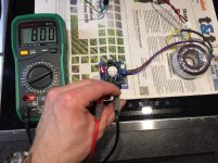
Here's a couple of shots from my setup. Obviously you need to use a sink for the LM regulator when loading it. In the first picture I have a 230/2x9 V trafo and the regulator is set to 8 VDC.
Attachments
Hello Morde, thanks a lot for the pics. On my board, the silkscreen is missing for one GND (next to the screwhole). Since there are 3*Vo+/GND, is it possible to connect at least two devices simultaneously or is it preferred to use a second board? I was thinking about driving the analog part of the DAC with a single board and use another board for the Pi and a HDD. My toroid has two secondaries. Regards, ka phi
Last edited:
Hi,
Is still available?
I need at least 2 pieces. Thanks
Hi,
Currently I have only one left. But you can find gerbers somewhere in the thread and order your own PCBs from fab house.
Regards,
Aleš
Hi,
Is still available?
I need at least 2 pieces. Thanks
Hi,
Check your PM
")
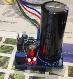
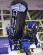
Just build a 12V / 5A power supply on Ales pcb ... and again it works flawless.


Leaving it running at half a day and it hardly gets warm at all.
Powercord design picks up no ripple at all at 50Hz !


Because of the big smootingcapacitors i added a softstart.
Again with a very nice and smooth output till 100kHz.

Leaving it running at half a day and it hardly gets warm at all.
An externally hosted image should be here but it was not working when we last tested it.
An externally hosted image should be here but it was not working when we last tested it.
Powercord design picks up no ripple at all at 50Hz !
Because of the big smootingcapacitors i added a softstart.
Again with a very nice and smooth output till 100kHz.
These boards are very inexpensive--I'll say that---but I have some serious gripes about them:
- The "pads" for capacitor C3---across the adjustment resistor are far too small for a normal 10uF electrolytic cap, and there's VERY little room to mount such. Does it really need to be only able to use a surface-mount cap?
- The LEDs are in a VERY strange place---why in the adjustment leg instead of across the output like normal?
- The holes for the variable resistor are not drilled for a normal VR footprint
- Capacitor C1 should be made to accomodate 35mm caps
- It's like too much effort was made to make it SUPER small, when DIY projects shopuld be EASY to build instead
Hi,
Question about the LDOs...
About the output noise level specified in the data sheets. Do you know if it is the inner noise of the component or the maximum output noise in output whatever is the input noise ? (or both) ?
What is the output noise of a ldo given for 100uV output noise is sypplied by a 0V noise intput ?
Thank you
Bernard
Hi,
I ordered them last year from DirtyPCBs, they are flawless.
- Status
- This old topic is closed. If you want to reopen this topic, contact a moderator using the "Report Post" button.
- Home
- Group Buys
- Linear regulator PCB (LM317, LT1085, LM338, LT1083)