Is that link for 10 of them?
Yes, it’s a 10pcs pack. Quite small, fits everywhere, really useful stuff.
Easy and fun to build even for a newbie like me.
Hi raoul,
Have you managed to build and test this PCBs?
BR,
Aleš
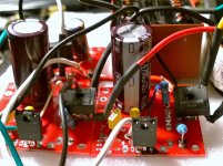
I'm not sure I've ever responded to this, sorry: never used them as intended, for LM317, LT1085, LM338, LT1083. Instead, I've used them for LT1963/LT3015 and LM78xx/79xx.
") Of course, few of the regulator's pins were not connected directly to the PCB and connections were done in the air, or PCB traces were cut and re-wired.
Of course, few of the regulator's pins were not connected directly to the PCB and connections were done in the air, or PCB traces were cut and re-wired.However, 90% of the traces were used, so I'm happy. Also, PCB board was of a very good quality, so I'm quite happy.
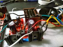
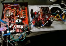
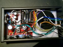
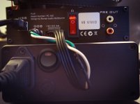
I've also attached few pics with the test PSU I've made almost 1 year ago to test a PCB board from a piece of equipment (PLAY V1.6 from Burson). There are 3 linear regulators: LM7812, LM7815, LM7918.
Not the best looking PSU, but everything worked as expected, so I'm quite happy! This replaced the power brick and internal XLSEMI boost-converters.
L.E.: Regulators are Japanese NJM, because I've seen better specs than similar regulators from ST, TI etc.
Not the best looking PSU, but everything worked as expected, so I'm quite happy! This replaced the power brick and internal XLSEMI boost-converters.
L.E.: Regulators are Japanese NJM, because I've seen better specs than similar regulators from ST, TI etc.
Attachments
Last edited:
I have a couple of the later versions of these PCBs that I would be happy to sell on if of interest to anyone?
I also have several of the earlier PCBs, containing two regulator circuits per board.
PM me if of interest.
All sold now
Hi,
Sorry for my english.
Could you help me please?
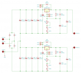
I'd like to use it in a symmetrical variant with an one-sided panel.
Is my schematic OK? (Changes: 1*4 4A diodes instead 2*4 2A; 2*4 2700uF caps instead 2*1 10000uF.)
I need +-25V output. Is 29-0-29 input correct? (29=25+1+1+3 (output + rect.diode + rect.diode + lm338))
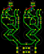
Is my PCB layout right? Blue and red lines are jumper wires on component side. SMD caps are on copper side.
Sorry for my english.
Could you help me please?
I'd like to use it in a symmetrical variant with an one-sided panel.
Is my schematic OK? (Changes: 1*4 4A diodes instead 2*4 2A; 2*4 2700uF caps instead 2*1 10000uF.)
I need +-25V output. Is 29-0-29 input correct? (29=25+1+1+3 (output + rect.diode + rect.diode + lm338))
Is my PCB layout right? Blue and red lines are jumper wires on component side. SMD caps are on copper side.
Attachments
Sorry for my english.
I apologize for my previous post.
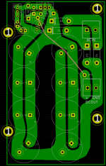
I realized my mistake and modified the original design to a multi-capacitor version.
The panel is rough because my ability to make PCBs at home is limited.
I left a gap between the capacitor columns so that the fixing hole of the IC could be accessed with a screwdriver.
I apologize for my previous post.
I realized my mistake and modified the original design to a multi-capacitor version.
The panel is rough because my ability to make PCBs at home is limited.
I left a gap between the capacitor columns so that the fixing hole of the IC could be accessed with a screwdriver.
Attachments
I do have some PCBs and I use them for fixed or variable voltages too. All you need os to respect the main schematic, based on the regulator used, while double checking the PCB traces and measure everything with a DMM.
Thank you. So looking at the schematic, do you just short C1 ground to C3 ground and ignore D5, R1 and D6 (as well as the adjustment section)?
Not sure, I don't have the PCB in front of me, but by looking to 1st page pictures seems that these caps are already paralleled. If you have such a PCB, just use a good light and check the traces, then simply follow the schematic from your regulator's datasheet. Depending on the regulator used, some small modifications might be needed, but nothing not to be handled with ease.
- Status
- This old topic is closed. If you want to reopen this topic, contact a moderator using the "Report Post" button.
- Home
- Group Buys
- Linear regulator PCB (LM317, LT1085, LM338, LT1083)