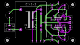
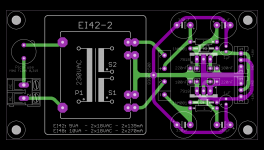
Gentlemen, I have layouted a simple PSU-PCB for use with the Calvin buffers.
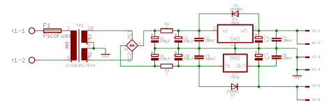
It uses a EI42 - 230VAC print-transformer and 7818 / 7918 voltage regulators.
The size of the PCB is 88 x 53 mm; the PCB is double-sided, made of 1.6mm FR4 with 70µm copper coating.
I have ordered 20 PCBs. The PCBs will be delivered in about 4 weeks.
The price for 2 PCBs incl. worldwide-shipping is 13€.
Please tell me, if you are interested having a pair of these PCBs.
Best regards - Rudi_Ratlos
Attachments
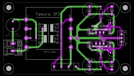
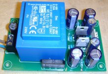
Bill, you are of course right, and I have layouted a neat PSU for the CALVIN-buffer (see attached image).
But: the used TAMURA-transformer (3FD-336), which will support both 115VAC and 230VAC primary, will not be "strong" enough to sink 2 CALVIN buffers!
So you need 1 PSU per CALVIN-Buffer PCB - and this has been the reason why I have hesitated to offer you this PSU.
I will happily offer you 10 of the 3FD-336 - PCBs for a very (!) decent price (10 PCBs is the minimum amount of PCBs to order), but it will then be your your job
to find some of fellow countrymen, who would like to have these PCBs as well.
Best regards - Rudi_Ratlos
Attachments
Rudi,
I see what you are saying, I have a few Salas shunt power supply boards I can use with a separate transformer. It just will not fit in the the case with the VCPre, no real big deal I can build it in a case of it own. I would not have issue buying 10 for myself if it could support 2 buffers, but as you point out the current output is not high enough to be useful for many projects.
Thanks for your efforts the same.
Bill
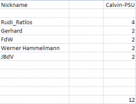
Gig, I am unhappy to tell you that all of my PSU - PCBs have already been sold.
I can do a new order, but the minimum amount of PCBs to order is 10 pcs.
One PCB will cost 4€.
The PCB will support 230VAC print-transformers only.
Best regards - Rudi_Ratlos
I can do a new order, but the minimum amount of PCBs to order is 10 pcs.
One PCB will cost 4€.
The PCB will support 230VAC print-transformers only.
Best regards - Rudi_Ratlos
Attachments
Hi Rudi,
I have only just discovered this thread.
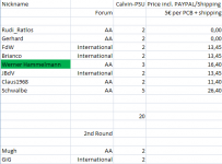
Does your ordered list include the early 'orders' from the original thread?
http://www.diyaudio.com/forums/group-buys/239776-calvin-buffer-paradise-7.html#post3679625
Many thanks,
Brian
I have only just discovered this thread.
Does your ordered list include the early 'orders' from the original thread?
http://www.diyaudio.com/forums/group-buys/239776-calvin-buffer-paradise-7.html#post3679625
Many thanks,
Brian
Hi,
Yes, it was intended as a standalone Buffer, or part of a preamplifier as You might see from its original thread.
It may be beefed up as a HP-driver or even as a low wattage power stage for loudspeakers.
As for the Q of how good it is, I think I may say ... satisfying. ;-)
jauu
Calvin
Yes, it was intended as a standalone Buffer, or part of a preamplifier as You might see from its original thread.
It may be beefed up as a HP-driver or even as a low wattage power stage for loudspeakers.
As for the Q of how good it is, I think I may say ... satisfying. ;-)
jauu
Calvin
Hi,
I found this thread not before Yesterday. I wished I had earlier, to be able to help improve the layout.
Unfortunately AndrewTs remarks didn't fell on fertile ground, as his critics about the layout is true. A single sided layout would suffice for this basic application. And rather doing it right singlesided, than implementing flaws doublesided.
I wished -even if the Buffer is opensource- the thread opener had contacted me early in a project he cited my name in, or asked some other knowledgeable person.
As the layout is, I wouldn't have recommended it for a production run because of its flaws, in special the gnd layout.
jauu
Calvin
Calvin, I am unhappy that you dislike the layout of the +/-18V PSU, used for your buffer; on the other hand, your comment is not raising a big concern for me.
I have been guided by two well-experienced members of this forum to layout the PSU as is, implementing a star-ground scheme, moving the small caps as close
as possible to the regulators, ..., until they finally said: "Perfect".
This is DIY: some like it this way, some like it the other way round.
I am very sure that this small PSU (50 x 100mm PCB-size) "will behave" very well, and I will post some pictures of the output-voltage rails, operating your buffer, once I have built it.
Best regards - Rudi_Ratlos
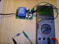
Gentlemen, I received the ordered prototype-PCBs (post #1) today and soldered one immediately.
I configured it like this:
470µF/35V - 1R - 470µF/35V at the input, 470µF/25V at the output.
I connected a load of 700Ohm (resulting in about 25mA) at the output.
The result:
I did some mathematic calculations today.
The C-R-C filter (??) in front of the input is not effective at all! I could as well have shorted the 1R - resistor!
I then calculated the value of the coil of a C-L-C - PI filter: 300mH at least! - no way to go on this small PCB (50x100mm).
Calvin is right then; the "implemented low-pass filter on the input " is not in effect!
On the other hand: my DMM shows an oscillation between 18.068V and 18.069V on the output! No more.
I will connect it to my Tektronix oscilloscope tomorrow and will measure the output-ripple in detail!
Please take into account: this small, dual voltage PSU does not cost more than 10€ with all of its components (PCB, transformer, regulators, ...) inclusive.
I therefore think that it is a real bargain!
Best regards - Rudi_Ratlos
Attachments
Last edited:
The C-R-C filter (??) in front of the input is not effective at all! I could as well have shorted the 1R - resistor!
I then calculated the value of the coil of a C-L-C - PI filter: 300mH at least! - no way to go on this small PCB (50x100mm).
1 Ohm is to low
") 10... and up will work (like AndrewT said). And it is no miracle-solve-all solution, as you said a coil would be better (but more expensive). But if you are willing to 'sacrifice' a bit of power, and contribute to global warming (a tiny bit (more than when using a coil)), then using a resistor of a somewhat (or is it 'some-watt' ) higher value is a good and cheap alternative (to the coil).
10... and up will work (like AndrewT said). And it is no miracle-solve-all solution, as you said a coil would be better (but more expensive). But if you are willing to 'sacrifice' a bit of power, and contribute to global warming (a tiny bit (more than when using a coil)), then using a resistor of a somewhat (or is it 'some-watt' ) higher value is a good and cheap alternative (to the coil).
Last edited:
- Status
- This old topic is closed. If you want to reopen this topic, contact a moderator using the "Report Post" button.
- Home
- Group Buys
- PSU for Calvin buffer