Started a layout but I tend to work slowly. I also have some obligations at home at the moment keeping me from spending extra time on those projects. I should be getting back to it in a few weeks.
When such time comes that I have something to show, I will start a new thread. Since PMI's absence has left some folks upset, and my project would end up being a competing one, I don't wish to post too much here.
If designing new pcb for cap multiplier than it would probably be good to change from ZVP/ZVN to BS170/BS250 because they are cheaper and easier to find (observing pinout). Also for pass transistors could be used IRF parts that metallicus69 used as substitutes (more power and lower Rds).
If designing new pcb for cap multiplier than it would probably be good to change from ZVP/ZVN to BS170/BS250 because they are cheaper and easier to find (observing pinout). Also for pass transistors could be used IRF parts that metallicus69 used as substitutes (more power and lower Rds).
In fact, my 'dead bug' prototype is showing excellent performance using BJT's for the differential amp and as a result I'm seriously thinking going that route, negating the sourcing of small MOSFETs. For pass devices I'm using Fairchild FQP47P06 and FQP50N06. Nice part about power MOSFETs is the pinout is AFAIK common to all except for lateral types, which don't suit the purpose here anyway. Just choose a low Rds type that is handy and drop them in. I'll likely include pads for TO-220 and TO-247 packages, and top or bottom mounting options.
In any event, all this discussion isn't related to PMI's group buy thread at the moment. I'll create a new thread for my own efforts soon.
Need help
Hello guys,
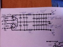
This year i managed to make some money to buy myself two trafos E+I 300VA@25+25v@5A bifilar secondaries windings for the a dual monos Jean Hiraga 30w "Super Class A amplifier". I want to make a separate 25-0-25V for the input and 30-0-30V just for the output tranies.
Wich solution is better for the best sound quality:
1. The schematic attached (one per single chanel) but with Mr Evil CM instead of the 0.22Ohm/25W resistors for the outputand another CM for the input.
2.The schematic attached as it is (one per single chanel) for the output and a separate Mr Evil CM for the input.
* Can i use a single CM for both inputs from a separate trafo (20+20VA)? Or i have to use separate CM for each channel?
*What is better to use: a separate trafo for CM of the input or take the AC current from the same trafo used for the input?
Thanks in advance
Hello guys,
This year i managed to make some money to buy myself two trafos E+I 300VA@25+25v@5A bifilar secondaries windings for the a dual monos Jean Hiraga 30w "Super Class A amplifier". I want to make a separate 25-0-25V for the input and 30-0-30V just for the output tranies.
Wich solution is better for the best sound quality:
1. The schematic attached (one per single chanel) but with Mr Evil CM instead of the 0.22Ohm/25W resistors for the outputand another CM for the input.
2.The schematic attached as it is (one per single chanel) for the output and a separate Mr Evil CM for the input.
* Can i use a single CM for both inputs from a separate trafo (20+20VA)? Or i have to use separate CM for each channel?
*What is better to use: a separate trafo for CM of the input or take the AC current from the same trafo used for the input?
Thanks in advance
Attachments
The CM should provide good enough isolation that it won't make a big difference how you connect them up. I would go for whichever is simplest or cheapest....Wich solution is better for the best sound quality...
PMI is no longer contactable, so there won't be any more boards unless someone else wants to make them.Any boards available? Thanks
I'd like 4 please.
The CM should provide good enough isolation that it won't make a big difference how you connect them up. I would go for whichever is simplest or cheapest.
PMI is no longer contactable, so there won't be any more boards unless someone else wants to make them.
Did you ever do a layout for single side boards so these could be etched?
No, but the original layout on my site is single-sided, so it wouldn't take a huge effort for someone (not me!) to turn it into a more general-purpose layout like PMI's.
Picking up the project again...
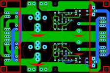
I know it has been a long time, but I'm finally getting back to the CM supply. When the time is right I'll create a new thread or continue in a prior thread of mine. Here's a peek. It is currently a 4" x 6" (101.5mm x 152.3mm) board and can accommodate 40mm snap in caps with 10mm LS two pin or 22.5mm LS four pin. Comments or suggestions welcome. It isn't quite finished but should be close to its final form.
BIG edit: I didn't notice this was an old Group Buy thread; my apologies - this should have been elsewhere.
Attachments
Last edited:
I know it has been a long time, but I'm finally getting back to the CM supply. When the time is right I'll create a new thread or continue in a prior thread of mine. Here's a peek. It is currently a 4" x 6" (101.5mm x 152.3mm) board and can accommodate 40mm snap in caps with 10mm LS two pin or 22.5mm LS four pin. Comments or suggestions welcome. It isn't quite finished but should be close to its final form.
Nice ideja

I would personally make a discrete dual rectifier at the input, instead of single one on photo, to maintain galvanic separation between transformer and amplifier ground. Faston conncectors are most recommended add on. Only one thing about mosfet tranzistor placement...I would position them, that they could be mounted to the bottom of the metal chassis. That would be simple and elegant solution

Nice ideja
I would personally make a discrete dual rectifier at the input, instead of single one on photo, to maintain galvanic separation between transformer and amplifier ground. Faston conncectors are most recommended add on. Only one thing about mosfet tranzistor placement...I would position them, that they could be mounted to the bottom of the metal chassis. That would be simple and elegant solution
+1
hello, i trimpot mr.evil cap multiplier so there no voltage drop.
no voltage drop- no heat mosfet. this ok? they all work still?
No voltage drop across the MOSFETs means the circuit will pass ripple from the input to the output. There should be about 2V between the source and drain of each pass MOSFET. Otherwise you aren't getting the benefit of the circuit.
Jeez, that's a new one donovas - never thought that C7 across the trimpot would make a difference - will try this myself - I learn something every day.
I haven't heard anyone here mention it, but I routinely use snubber networks (C-R + C) on transformer secondary windings (before the diodes), for a much quieter sound (see the Quazimodo tester thread for info) - suggest 'a look'.
I haven't heard anyone here mention it, but I routinely use snubber networks (C-R + C) on transformer secondary windings (before the diodes), for a much quieter sound (see the Quazimodo tester thread for info) - suggest 'a look'.
C7 isn't part of a snubber, it's to increase feedback at high frequencies. You can remove it if you don't like it and the circuit should still work, but it will be less stable.very good, thank you.
now, how make c7 irrelevant? i don't care snubber sound. no c7, sound better. but trimpot make noise. mechanical noise from trimpot it self!
Are you saying that you are getting noise from the pot, or are you just worried that you might do? The DC current through the pot is very small, and it never needs to be adjusted in use, so it shouldn't generate any more noise than a plain resistor.
- Home
- Group Buys
- Mr Evil's Capacitance Multiplier Power Supply PCB