Can I jump in at the last minute and take two boards? Thanks. -Freeman
No problem... as they say, u get what u pay for...(same thing applies to anyone else)
The spares I ordered went really fast after the first people who built boards from the last order posted pics in the other thread, so there is actually a waiting list (short one so far...Can I jump in at the last minute and take two boards? Thanks. -Freeman
) I'll make another order if necessary.Any similar transistor should do. Make sure the pinout matches. I have only actually tested with BC550/560 and BC546/556.PMI,
Is there any suggested replacement for 556/546? It is hard to source it and mouser charges ridiculous amount to ship.
Thanks
If you are having trouble sourcing parts, let me know before I start to ship (send a PM). I have spares for the BC546B/BC556B (~0.10/ea), and I am putting semiconductor kits together for some people.
PMI,
Thank you for this information. Will send a PM regarding this.
Thanks
Thank you for this information. Will send a PM regarding this.
Thanks
The spares I ordered went really fast after the first people who built boards from the last order posted pics in the other thread, so there is actually a waiting list (short one so far...
Any similar transistor should do. Make sure the pinout matches. I have only actually tested with BC550/560 and BC546/556.
If you are having trouble sourcing parts, let me know before I start to ship (send a PM). I have spares for the BC546B/BC556B (~0.10/ea), and I am putting semiconductor kits together for some people.
Post 52 in this thread:hello,
yesterday i`ve found thread where measurements of this PSU were shown. Could anyone link this thread cause I`m not able to find it today.
Thank you.
http://www.diyaudio.com/forums/powe...hed-capacitance-multiplier-6.html#post3568084
There are other useful links from the first post here, too.
The second order of PCBs arrived today, as scheduled!
I will take a few samples out and inspect them tomorrow. With any luck, the first boards will be ready to ship by the end of the day. Shipment confirmations will be made in Paypal for every shipment.
I can always make another order, if there is enough continued interest, but for the next few days I will be concentrating on getting boards and parts packed and shipped to people who have already paid.
I will take a few samples out and inspect them tomorrow. With any luck, the first boards will be ready to ship by the end of the day. Shipment confirmations will be made in Paypal for every shipment.
Most of the spares have been "allocated" now, so to speak. There is a waiting list, although a very short one.it's not too late?? Put me in for two, please.
Thank you.
I can always make another order, if there is enough continued interest, but for the next few days I will be concentrating on getting boards and parts packed and shipped to people who have already paid.
Capacitance Multiplier PCB Pics
There are pics of the prototype in the first post. I am now using that board with the through-hole version of Lazy Cat's VSSA amplifier. There are more details about that in the PeeCeeBee thread. There are also other pictures and some test results in the second one of Mr Evil's threads on the original design.
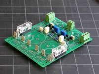
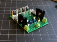
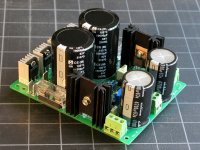
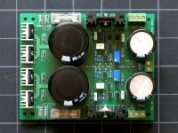
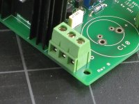
This is one of my test boards, from the last pcb order. This board has screw connectors installed instead of the Faston-type terminals to make wiring changes a bit more convenient during testing, and it uses the ON-Semi MSRF860 rectifier diodes so I can test at the maximum voltage and heatsink load.
There are pics of the prototype in the first post. I am now using that board with the through-hole version of Lazy Cat's VSSA amplifier. There are more details about that in the PeeCeeBee thread. There are also other pictures and some test results in the second one of Mr Evil's threads on the original design.
This is one of my test boards, from the last pcb order. This board has screw connectors installed instead of the Faston-type terminals to make wiring changes a bit more convenient during testing, and it uses the ON-Semi MSRF860 rectifier diodes so I can test at the maximum voltage and heatsink load.
Attachments
Last edited:
If i use a 2x40V Ac transformer what would be the output voltage. I intend to use it with VSSA also.
! ( too high ).40V AC (rms) secondary will be about 42V at idle, 42*1.414 ~ +/- 60V DC unregulated at the main reservoir cap!
This is too high for VSSA (unless you are building one of the variants with higher supply rails).
Absolute maximum supply voltage for Lazy Cat's VSSA circuit is +/-45V.
I am not completely sure what you mean by "stabilize", regulate/regulator?Let me ask in a different way
Yes, but what it does is regulate the pass transistor voltage drop (Vdrop), and so indirectly, it lowers the output voltage by the same amount. However, the output voltage will still rise and fall with line and load changes, while the Vdrop will stay the same. (This is a good thing, IF you want the best possible filter with the lowest possible "voltage loss" - most people want this - greatest possible benefit at lowest cost.)
A conventional regulator in a variable linear power supply acts the opposite way. The output voltage will stay where you set it, while the voltage drop across the pass transistor will rise and fall depending on line and load changes. This is great if you want an output adjustable over a large range, and which will stay where you set it, regardless of the voltage at the input. At high current this generates larger power losses, and lots of heat.
You can use the circuit board this way, but not with this BOM. There is a post in Mr Evil's thread on how to do this, with different components, and you will also need bigger heatsinks. (second thread linked from the first post here)
Last edited:
Current PCB Status
Almost all of the PCB's that have been paid for so far have been shipped. Not all of the Paypal notices have been marked as shipped, but that will be done by the end of this weekend.
Only exception are a few boards with extra parts requested after the initial order was placed. Those will ship 4-5 days later if parts had to be ordered.
There are a couple sets unpaid, a couple where I have either not received a mailing address I can match to a diyaudio name, or where the amount paid does not match the number of boards requested, one set paid and being held until the owner returns from vacation etc.
If you intend to pay later than this weekend, please contact me so I can set your boards aside, thanks!
Last edited:
Capacitance Multiplier Component Selection Notes
The choice of components was made so a complete set can be bought from one source, Mouser. If you intend to buy from this distributor, please check out the links to lists of parts on mouser.com in the first post, they can save a little time, because you will not have to enter parts one at a time. The lists can be saved as your own BOM, combined, edited, etc.
Mosfets, Q7-Q10:
Since the BOM was posted, ZVN2106A is out of stock and on backorder at Mouser in the US, but it is available from Newark (and on sale there). The closest alternative for the ZVN2106A/ZVP2106A Mosfets I have found from the same manufacturer, and stocked at Mouser is this pair:
ZVN3306A / ZVP3306A
(There are also other alternatives and discussion in Mr Evil's thread, which is linked in the first post.)
Rectifier Diodes (D1-D4):
The specified diode is MBR10100, 10A 100V max reverse voltage. Schottky diodes have very low forward voltage drops at the typical expected suply currents, but a very small U-shaped heatsink is still required, because Schottky diodes work better when cool-to-warm. (A small piece of aluminum will work just as well).
The 100V reverse voltage rating corresponds to a transformer secondary voltage of about 35V maximum, or about 32~33V rated voltage. Above this limit, a more conventional rectifier diode with higher reverse voltage should be used.
C11-C12:
These are optional (yes, really) When using the PSU in its simplest configuration, with Schottky diodes, reservoir caps, and nothing connected to the unregulated terminals (DC+ and DC- on the silkscreen), these are not required.
They can be used as conventional hf decoupling for anything connected to the unregulated/unfiltered terminals, or for some additional noise suppression when conventional rectifier diodes are used.
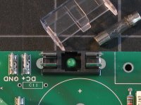
Indicator LEDs (LED1, LED2):
The LED was specified as 3-mm to fit inside the fuse holder, to save space and light up the fuses from below. (It is something I kept from Mr Evil's original design). 5-mm was never intended to fit. 3-mm LEDs are supplied with the boards. The ones shipping now are green with a clear lens, and are the "short-lens" type. However, a standard 3-mm, 20 mA LED of any color will fit.
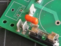
LED series resistors (R13-R14):
These also serve as very small bleed resistors for the reservoir caps. If the LED is not used, the LED pads should be shorted on the bottom side of the board. The value and/or the 1/4 watt rating should be adjusted for the intended supply voltage. 3.3K 0.25 watt is a minimum value. Examples of power supply voltages and 1/4 watt resistor values:
<30V 3.3K~4.7K
<40V 6.8K~10K
<50V 10K~15K
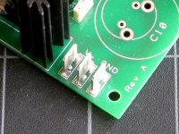
Connectors:
The pcb will accept either Faston-type connectors, or terminal blocks, 2 and 3-position, 5~5.08mm pin spacing. The only connections that require single-point Fastons are AC1-AC4, for leads from the transformer secondary windings.
There is a ground connection for every power input and output. Whether using Fastons or screw terminals, you only need to assemble those you intend to use.
Terminal Block Examples:
Newark: MC24366 and 24367
Mouser: Phoenix p/n 1935161 and 1935174
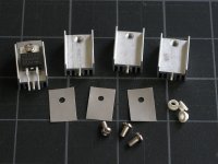
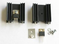
TO-220 Insulators:
Not required, but recommended, because the chance of a short to rectifier diode heatsinks, or to the pass transistor heatsink is a definite possibility when testing the supply or adjusting Vdrop. Any silicone insulator will do, because in most cases there is not a lot of heat dissipated. Mica insulators are only required if high idle currents are expected (for high-bias or Class-A amplifiers).
TO-220 Mounting Kits:
A typical mounting kit consists of a plastic shoulder washer, a 3-mm machine screw, and depending on whether the heatsink hole is threaded or not, a lock washer and 3-mm nut. Screws for tapped heatsinks should be 6-8 mm long, 8-10-mm if a nut is required.
The choice of components was made so a complete set can be bought from one source, Mouser. If you intend to buy from this distributor, please check out the links to lists of parts on mouser.com in the first post, they can save a little time, because you will not have to enter parts one at a time. The lists can be saved as your own BOM, combined, edited, etc.
Mosfets, Q7-Q10:
Since the BOM was posted, ZVN2106A is out of stock and on backorder at Mouser in the US, but it is available from Newark (and on sale there). The closest alternative for the ZVN2106A/ZVP2106A Mosfets I have found from the same manufacturer, and stocked at Mouser is this pair:
ZVN3306A / ZVP3306A
(There are also other alternatives and discussion in Mr Evil's thread, which is linked in the first post.)
Rectifier Diodes (D1-D4):
The specified diode is MBR10100, 10A 100V max reverse voltage. Schottky diodes have very low forward voltage drops at the typical expected suply currents, but a very small U-shaped heatsink is still required, because Schottky diodes work better when cool-to-warm. (A small piece of aluminum will work just as well).
The 100V reverse voltage rating corresponds to a transformer secondary voltage of about 35V maximum, or about 32~33V rated voltage. Above this limit, a more conventional rectifier diode with higher reverse voltage should be used.
C11-C12:
These are optional (yes, really
) When using the PSU in its simplest configuration, with Schottky diodes, reservoir caps, and nothing connected to the unregulated terminals (DC+ and DC- on the silkscreen), these are not required.They can be used as conventional hf decoupling for anything connected to the unregulated/unfiltered terminals, or for some additional noise suppression when conventional rectifier diodes are used.
Indicator LEDs (LED1, LED2):
The LED was specified as 3-mm to fit inside the fuse holder, to save space and light up the fuses from below. (It is something I kept from Mr Evil's original design). 5-mm was never intended to fit. 3-mm LEDs are supplied with the boards. The ones shipping now are green with a clear lens, and are the "short-lens" type. However, a standard 3-mm, 20 mA LED of any color will fit.
LED series resistors (R13-R14):
These also serve as very small bleed resistors for the reservoir caps. If the LED is not used, the LED pads should be shorted on the bottom side of the board. The value and/or the 1/4 watt rating should be adjusted for the intended supply voltage. 3.3K 0.25 watt is a minimum value. Examples of power supply voltages and 1/4 watt resistor values:
<30V 3.3K~4.7K
<40V 6.8K~10K
<50V 10K~15K
Connectors:
The pcb will accept either Faston-type connectors, or terminal blocks, 2 and 3-position, 5~5.08mm pin spacing. The only connections that require single-point Fastons are AC1-AC4, for leads from the transformer secondary windings.
There is a ground connection for every power input and output. Whether using Fastons or screw terminals, you only need to assemble those you intend to use.
Terminal Block Examples:
Newark: MC24366 and 24367
Mouser: Phoenix p/n 1935161 and 1935174
TO-220 Insulators:
Not required, but recommended, because the chance of a short to rectifier diode heatsinks, or to the pass transistor heatsink is a definite possibility when testing the supply or adjusting Vdrop. Any silicone insulator will do, because in most cases there is not a lot of heat dissipated. Mica insulators are only required if high idle currents are expected (for high-bias or Class-A amplifiers).
TO-220 Mounting Kits:
A typical mounting kit consists of a plastic shoulder washer, a 3-mm machine screw, and depending on whether the heatsink hole is threaded or not, a lock washer and 3-mm nut. Screws for tapped heatsinks should be 6-8 mm long, 8-10-mm if a nut is required.
Attachments
- Home
- Group Buys
- Mr Evil's Capacitance Multiplier Power Supply PCB