Ooo, how sweet is to receive letters from Alfred! As I said, the next day from BDL got its parcel, I got mine (that's what I said in reply to BDL)
When the secretary of the company I work for, saw the little PCB's, she asked me if they are some bijoux, pendants or earrings. Like the Paradise pcb's, very good quality.
Thank you
Alfred, Calvin and the others
Want me to put some chocolates next time ?

I am having problems in getting matching voltage across the input and CCS jFETs.
The Cascoding jFET is very high Idss to give the required Vds across the other jFETs.
I cannot use the manufacturers' method of low duty cycle Idss measurement.
Instead, after trying both bf245c and then j111, as the cascodes to my lsk170bl, I inserted sockets into my third PCB.
This allowed me to select near equal cascode voltages from the upper jFETs.
0.1" (2.54mm) pitch sockets don't fit. The pads appear to be ~ 1.8mm pitch.
I really needed a little jig to test measure the cascode voltages before soldering into the PCBs.
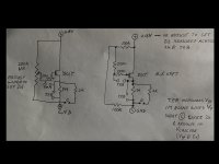
A couple of pics to follow showing the circuit and set up.
The Cascoding jFET is very high Idss to give the required Vds across the other jFETs.
I cannot use the manufacturers' method of low duty cycle Idss measurement.
Instead, after trying both bf245c and then j111, as the cascodes to my lsk170bl, I inserted sockets into my third PCB.
This allowed me to select near equal cascode voltages from the upper jFETs.
0.1" (2.54mm) pitch sockets don't fit. The pads appear to be ~ 1.8mm pitch.
I really needed a little jig to test measure the cascode voltages before soldering into the PCBs.
A couple of pics to follow showing the circuit and set up.
Is Vth the pinch off voltage?
Then measuring Vpinch off does not give a good indication of the resulting cascode voltage when installed in the circuit.
I am finding that the very variable gm of typical jFETs results in Vgs at the operating current being very different from what might be indicated by measuring and selecting by Vpinch off alone.
If you were to 2point measure your devices at Id~10uA and then at operating current, you will find that you can select devices that will give a fairly good cascode voltage match and this will remain good over a reasonable range of operating temperature.
My first bf245c selected by Vpinch off gave cascode voltages of ~ -1.5Vgs and -2.7Vgs.
This places the two jFETs inside their respective cascode loops, at very different operating points and this discrepancy will allow excessive drift with temperature changes.
My second using Vpinch off for J111 resulted in cascode of ~-5Vgs and -6.9Vgs
My third PCB using selecting Vgs at ~8mA resulted in ~-6.7Vgs and ~-6.4Vgs
This proves to me that single point measuring and selecting does not give reasonable cascode voltage matching.
Last edited:
I take it back.
Much of post367 is drivel.
I was using the completed 3rd PCB with the sockets for the cascoding FETs.
swapping the FETs in until I found a pair that gave near matching cascode voltage. Then when I checked the Vp found they were way out.
Using the jig:
I selected Vcascode and inserted the selected into the 3rd PCB. Gives a very good match.
Went back and checked Vp. Also very close.
I then measured the remainder of my stock 19 off J111 and measured Vp and Vcascode in the jig.
There is very good correlation from Vp to Vcascode. Only 1 out of the 19 gave an odd pair of voltages.
Attachments
Interesting.... thanks for all that work and sharing your results, obviously it pays off to check twice! I should measure mine as well then again (yes I admit my lazyness, after assembly I was so eager to listen that I didnt re-measure ) and now my Paradise is with a friend......
Anyway, the assembly guides have been updated, fixing some BOM issues and I also added a stuffing diagram with the component designators, access through the link list in my signature.
) and now my Paradise is with a friend......Anyway, the assembly guides have been updated, fixing some BOM issues and I also added a stuffing diagram with the component designators, access through the link list in my signature.
Trannies for Calvin GB update
Hi folks
All the trannies are on the way now
Before you start with the boards please read "Alfreds" new Link-list
(Calvin buffer assembly guide) and "Calvins" clarifications. Well done!!!!!!
I had a fault on my boards as well. But now is all clear.
Happy days
Werner
Hi folks
All the trannies are on the way now
Before you start with the boards please read "Alfreds" new Link-list
(Calvin buffer assembly guide) and "Calvins" clarifications. Well done!!!!!!
I had a fault on my boards as well. But now is all clear.
Happy days
Werner
Interesting.... thanks for all that work and sharing your results, obviously it pays off to check twice! I should measure mine as well then again (yes I admit my lazyness, after assembly I was so eager to listen that I didnt re-measure
Anyway, the assembly guides have been updated, fixing some BOM issues and I also added a stuffing diagram with the component designators, access through the link list in my signature.
.... and there was another bug.... should be fixed now (thanks a lot Werner!!!) The link remains the same.
Alfred culd you please post a guide for very dumb peoples (like me) on matching the Jfets
Tanks
I also have a little trouble with matching here.
I determined Vp of the 2SK170 and PN4391 I used with this method. Apparently it is a little bit coarse, but I assumed I only needed to get good relative values.
Vp of the SK170 was in the range of -0.63 V to -0.64 V, IDSS around 9-9.5 mA
Vp of the PN4391 was around -6.5 V
Still I get a relatively large DC offset at the output of around 350 mV on one channel and 450 mV on the other. The 2k trimpot only can adjust it within about +-50mV, so I can´t set it to zero.
Despite proper matching within the 2SKs and PN-transistors, do they have to fit to each other? So do I need a specific 2SK170 Vp (or IDSS) range together with the right PN4391 Vp-range ? The built manual states around 8-8.5 mA IDSS for the 2SK170 so I´m a little higher here. Is this ok?
Or is it crucial to set up Andrews measurement setup from post 368?
- Status
- This old topic is closed. If you want to reopen this topic, contact a moderator using the "Report Post" button.
- Home
- Group Buys
- Calvin Buffer for Paradise