Jorge: METAL and I will definitely offer this PCB in a group-buy. METAL is currently re-working the µProcessor's software (firmware)
to include the changes (f.e.: Soft-Power-On interface, HTBypass interface, ...), while I do the layout-changes
and keep the documentation up-to-date.
I suppose to start the group-buy next week, but we have to settle upon what I will offer in this group-buy (PCBs, pre-programmed µProcessor,
for sure, what else?) first.
Wineds: the schematics are posted in the documentation ("Builder's Manual") that I will send to all participants of the group-buy.
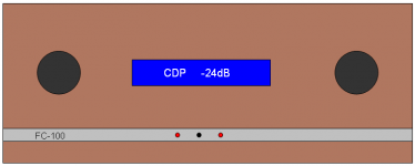
The VCPre is communicating its status on a 1x16 chars, HD44780 compatible LCD display. I will use a display with 9mm big letters.
You may use the display, but you need not.
The status of the source selection relays, the HTBypass relay and the Soft-Power-On relay will be reported on LEDs as well.
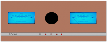
Find attached 2 pictures.
The left one shows how my front panel will look like, while the right one shows the front panel of a German DIY-friend of mine.
He is using McIntosh-like panel meters that are driven from a small DIY-PCB.
Best regards - Rudi_Ratlos
to include the changes (f.e.: Soft-Power-On interface, HTBypass interface, ...), while I do the layout-changes
and keep the documentation up-to-date.
I suppose to start the group-buy next week, but we have to settle upon what I will offer in this group-buy (PCBs, pre-programmed µProcessor,
for sure, what else?) first.
Wineds: the schematics are posted in the documentation ("Builder's Manual") that I will send to all participants of the group-buy.
The VCPre is communicating its status on a 1x16 chars, HD44780 compatible LCD display. I will use a display with 9mm big letters.
You may use the display, but you need not.
The status of the source selection relays, the HTBypass relay and the Soft-Power-On relay will be reported on LEDs as well.
Find attached 2 pictures.
The left one shows how my front panel will look like, while the right one shows the front panel of a German DIY-friend of mine.
He is using McIntosh-like panel meters that are driven from a small DIY-PCB.
Best regards - Rudi_Ratlos
Attachments
@Voxxonline: I do see no reason, why this is not doable.
The VCpre needs 2 voltages: 5VDC (7805) for the analog and digital world and 6VDC (7806) for the Motor-H-Bridge
to drive the motorized potentiometer.
The power-consumption of the VCPre is: 1-2 source relays (source-input and HTBypass, if HT is selected), 2-3 LEDs
(Active/Sleep-LED, 1-2 source-input relay LEDs), LDR-LED current, LCD display, µProcessor: round about 100mA.
The motorized-potentiometer needs about 100mA if processed.
I am not aware of any hum or "electronic smog" that the VCPre generates, nor do the German DIYers, who have already built the VCPre.
Best regards - Rudi_Ratlos
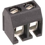
Hi Rudi, nice project. I would not use Molex KK for 230 V though. Better use a Phoenix MKDS for that. If you use a FR5 fuse it will fit.
Did you measure the device ? The transformer is pretty close to the audio circuitry. I think your GB will be a successful one as it is a complete versatile device. A buffer would have made it suitable for preamp use with separate power amps.
Did you measure the device ? The transformer is pretty close to the audio circuitry. I think your GB will be a successful one as it is a complete versatile device. A buffer would have made it suitable for preamp use with separate power amps.
Last edited:
@Voxxonline:
I am currently calculating prices (they depend of course upon the amount of orders), but I can give you the size of the PCBs immediately:
VCPre - PCB: size is 100 x 100mm
SPO - PCB: size is 80 x 70mm
HT - PCB: size is40 x 29mm
Best regards - Rudi_Ratlos
P.S. Jean-Paul: I will look for PHOENIX MKDS in my EAGLE-library.
That depends on the input impedance of this pre. The Subbu DAC does not like very low impedances. I take the liberty of asking some questions to Rudi:
1. What is the input impedance of the VCPre ?
2. At what load starts it to choke ?
3. Why no buffer at the output ?
That is better Rudi. Don't you think the SPO tracks run too close to AC pins of the transformer ? Also upper 230 V AC track from the fuse to the primary pin can be adjusted so that it stays further away.
* the whole input section can be moved somewhat closer to the upper side of the PCB. The further away from the transformer the better it is.
1. What is the input impedance of the VCPre ?
2. At what load starts it to choke ?
3. Why no buffer at the output ?
Jean-Paul: here we are.
Best regards - Rudi_Ratlos
That is better Rudi. Don't you think the SPO tracks run too close to AC pins of the transformer ? Also upper 230 V AC track from the fuse to the primary pin can be adjusted so that it stays further away.
* the whole input section can be moved somewhat closer to the upper side of the PCB. The further away from the transformer the better it is.
Last edited:
Jean-Paul, the input impedance varies between 10K - 15K, depending of potentiometer's value.
I designed this PCB having in mind, to integrate it into my amplifer's cabinet.
I do not need a buffered output in this case.
I will think about giving the PCB a buffer (maybe on the HTBypass-PCB).
Concerning the layout: the SPO- and upper 230VAC-track issues are cleared.
To move the input section closer to the upper side of the PCB will take some time. But I will do.
Best regards - Rudi
It's a very bold statement. Did You try this or You think this.Jean-Paul, the input impedance varies between 10K - 15K, depending of potentiometer's value.
Basic problem when you make a potentiometer with two LDR is very, very large differences in input impedance. From a few hundreds ohms to megaohms.
To show You how it works let the potentiometer at low volume. Current throw led diode of the LDR is 15mA. Paralell resistance in this case is 50-60 ohms and series resistance must be 300-500k if you need low volume. This is not 10-15k.
Preamp with LDR need buffer at the input and at the output
Impuls, please have a look at this thread:
http://www.diyaudio.com/forums/anal...uator-new-passive-preamp-462.html#post3015694
For example: post #4613.
Best regards - Rudi_Ratlos
http://www.diyaudio.com/forums/anal...uator-new-passive-preamp-462.html#post3015694
For example: post #4613.
Best regards - Rudi_Ratlos
ok graph is looking good. I start from the lowest volume. If you put high current throw Led, life time of this led is very short. I put my LDR at 15mA max. Resistance at this current is 50-60 ohms. If you want 70db regulated volume series resistance must be very high.
I made shunt type with fixed series resistor and LDR as parallel resistance. Parallel to LDR I put two relays for three quieter value of the volume. With fixed resistor is 6db lowest max signal but impedance is always between 10-20k
I made shunt type with fixed series resistor and LDR as parallel resistance. Parallel to LDR I put two relays for three quieter value of the volume. With fixed resistor is 6db lowest max signal but impedance is always between 10-20k
Guten Abend Rudi, simple JFET buffers would still be beneficial. For some reason I am reluctant with using non linear parts (as LDRs are) for volume control in audio but it is probably prejudice. I feel a lot better with stepped attenuators.
Always non rational stuff in audio. Wait for it and I will ask to provide for pads for a stepped attenuator But I really like the whole shebang on one PCB as I am in the same secret club of non modular thinking DIYers that like to swim against the current. Modular approach = wiring of several PCBs with countless connectors ....The Horror !
Now would be the moment to think about the size of the board. Make it slightly larger and you can add JFET buffers and have a larger distance between the transformer and the input/output circuitry. Fourth input would be possible too. Drawback: you will need symmetrical supplies when using buffers or use buffers with asymmetrical supplies coupled with those dreaded parts called capacitors... It would be a device that is even more versatile and suitable for standalone use as a separate preamp too.
Always non rational stuff in audio. Wait for it and I will ask to provide for pads for a stepped attenuator
But I really like the whole shebang on one PCB as I am in the same secret club of non modular thinking DIYers that like to swim against the current. Modular approach = wiring of several PCBs with countless connectors ....The Horror ! Now would be the moment to think about the size of the board. Make it slightly larger and you can add JFET buffers and have a larger distance between the transformer and the input/output circuitry. Fourth input would be possible too. Drawback: you will need symmetrical supplies when using buffers or use buffers with asymmetrical supplies coupled with those dreaded parts called capacitors... It would be a device that is even more versatile and suitable for standalone use as a separate preamp too.
Last edited:
Jean-Paul, thank you very much for your advices and remarks.
Regarding the position of the input-section in regard to the transformer's position: shifting the input-section as high as possible to the upper
PCB-border would result in a 3mm bigger distance from the transformer (but costs a very lot of work).
Nobody is bound to solder the transformer on the PCB.
You can put the transformer elsewhere in your case and run 2 wires to the rectifier.
But as I told you before: neither I nor the German DIY'ers, who have already build the VCPre (the previous PCB-version),
are aware of any noise that the transformer generates.
Regarding the use / the inclusion of a buffer: the "famous buffers" (f.e. DIAMOND buffer, Walt Jung buffer, ...) that I know,
all use a dual power-supply (f.e. +/-15VDC).
The VCPre provides only a single voltage: 5VDC.
If somebody knows a simple and "nice" buffer that can be operated from a single 5VDC supply: please tell me.
Best regards - Rudi_Ratlos
Looking better every time I check in. I will probably not use the transformer on board so that won't be an issue, and will probably have a DAC and some sort of buffer anyway. Would it be easy to bypass the power supply for the LDR section? Having a DAC in the same case I will have a good quality PS in place already. I love the single board solution and look forward to incorporating it into my next project. Thanks Rudi.
But as I told you before: neither I nor the German DIY'ers, who have already build the VCPre (the previous PCB-version),
are aware of any noise that the transformer generates.
Measured or listened ?
If somebody knows a simple and "nice" buffer that can be operated from a single 5VDC supply: please tell me.
Non existent, at least not good sounding with enough headroom. You could do it Pass B1 style but you will need 24 V for that. Or 2 x 9 V without coupling caps.
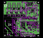
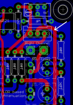
Billyk: the red track on the PCB's component-side, indicated by the white arrow, is the track that supplies 5VDC to the
LDR Attenuation Section (to the potentiometer that controls the current that is flowing through the LEDs of the LDRs).
I can of course put a jumper there, to make it possible to supply the needed 5VDC from another PSU.
How much is the output-impedance of your DAC?
Jean-Paul: I have listened and measured, using my Tektronix 465B oscilloscope.
I have fed a square wave and a sine wave to the input-selector and looked at the resulting output.
I could neither detect any "deformation" of the signals nor any noise.
Best regards - Rudi_Ratlos
Attachments
- Status
- This old topic is closed. If you want to reopen this topic, contact a moderator using the "Report Post" button.
- Home
- Group Buys
- Versatile and comfortable passive pre-amp