Gentlemen,
my DIY-friend METAL and I have been working for quite a while on a passive pre-amp that shall be versatile (give us all the functionality
that we need) and comfortable, so we can sit in our armchair and control everything per remote-control-unit.
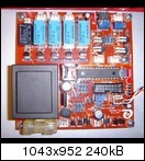
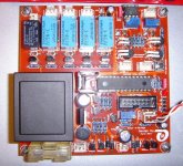
This is the current result of our project:
http://abload.de/img/display012a0xwe.jpg
This PCB (I call it VCPre hereafter) has the following functionality:
- Source selection of up to 3 input sources
- Mute function
- Attenuation, either based on a LDR - solution or a traditional AUDIO potentiometer
- Support of motorized potentiometers
- Display of attenuation
- Display of current temperature of your heatsinks
- Implementation of a Standby / Resume-from-Standby function for your amplifier
- Status-display on a 1x16chars LCD module
- Every function can be controlled by an infrared remote-control unit
The functionality of the VCPre is accomplished by the use of a PIC 16F886 µProcessor.
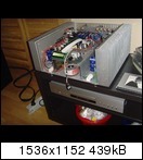
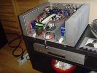
I myself am using the current VCPre PCB-version in the build of my FC-100 amplifier, it works flawlessly, and I did not yet receive any complaint
from any of the German DIYers, who have already installed the PCB.
http://abload.de/img/neverbeforehavelisten5hzwb.jpg
If there is some interest, I will start a group-buy offering the PCB(s), documentation, pre-programmed µProcessor, hard-to-get components (if any), ...
Best regards - Rudi_Ratlos
my DIY-friend METAL and I have been working for quite a while on a passive pre-amp that shall be versatile (give us all the functionality
that we need) and comfortable, so we can sit in our armchair and control everything per remote-control-unit.
This is the current result of our project:

http://abload.de/img/display012a0xwe.jpg
This PCB (I call it VCPre hereafter) has the following functionality:
- Source selection of up to 3 input sources
- Mute function
- Attenuation, either based on a LDR - solution or a traditional AUDIO potentiometer
- Support of motorized potentiometers
- Display of attenuation
- Display of current temperature of your heatsinks
- Implementation of a Standby / Resume-from-Standby function for your amplifier
- Status-display on a 1x16chars LCD module
- Every function can be controlled by an infrared remote-control unit
The functionality of the VCPre is accomplished by the use of a PIC 16F886 µProcessor.
I myself am using the current VCPre PCB-version in the build of my FC-100 amplifier, it works flawlessly, and I did not yet receive any complaint
from any of the German DIYers, who have already installed the PCB.

http://abload.de/img/neverbeforehavelisten5hzwb.jpg
If there is some interest, I will start a group-buy offering the PCB(s), documentation, pre-programmed µProcessor, hard-to-get components (if any), ...
Best regards - Rudi_Ratlos
Attachments
Last edited:
Not so fast, Patrick.
I like to explain in detail the features of the VCPre and collect your impressions, thoughts, wishes for enhancements, ..., first.
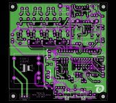
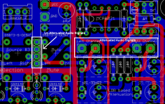
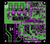
This is the main PCB:
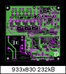
http://abload.de/img/vcprej7xef.png
Its size is 100 x 100mm, double-sided, top-quality.
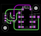
If you like to power-on/off your amplifier by your infrared control unit as well, I offer you a small Soft-Power-On PCB.
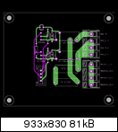
http://abload.de/img/spoqra3m.png
The SPO-PCB is connected to the VCPre-PCB by a 4-pole connector on the left side (above the small transformer) of the VCPre-PCB.
The reasons, why I layouted the Soft-Power-On on a PCB of its own, are:
- you can install the VCPre in a case of its own and connect it to the SPO-PCB, which is installed in your amplifier's case
- you can install both PCBs in different locations in your amplifier's case, separating the mains from the audio-section
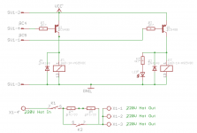
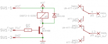
This is the schematics of the Soft-Power-On:
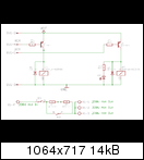
http://abload.de/img/image3b4qmh.png
As long as relay K1 is open, no current will flow at all.
After K1 is closed, current will flow through the NTCs (is limited by them) to prevent your fuse from being blown by the inrush current.
When, after some time, K2 is closed, the NTCs are bypassed and current can flow unhindered.
You can of course implement the timing with analog components.
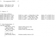
In this project METAL and I used the software-versatility of the PIC µProcessor.
This is for example the part of the software that switches off the amplifier (entering standby-mode):
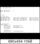
Easy! Isn't it?
If you have any questions about the functionality of the VCPre - tell me.
Best regards - Rudi_Ratlos
I like to explain in detail the features of the VCPre and collect your impressions, thoughts, wishes for enhancements, ..., first.
This is the main PCB:

http://abload.de/img/vcprej7xef.png
Its size is 100 x 100mm, double-sided, top-quality.
If you like to power-on/off your amplifier by your infrared control unit as well, I offer you a small Soft-Power-On PCB.

http://abload.de/img/spoqra3m.png
The SPO-PCB is connected to the VCPre-PCB by a 4-pole connector on the left side (above the small transformer) of the VCPre-PCB.
The reasons, why I layouted the Soft-Power-On on a PCB of its own, are:
- you can install the VCPre in a case of its own and connect it to the SPO-PCB, which is installed in your amplifier's case
- you can install both PCBs in different locations in your amplifier's case, separating the mains from the audio-section
This is the schematics of the Soft-Power-On:

http://abload.de/img/image3b4qmh.png
As long as relay K1 is open, no current will flow at all.
After K1 is closed, current will flow through the NTCs (is limited by them) to prevent your fuse from being blown by the inrush current.
When, after some time, K2 is closed, the NTCs are bypassed and current can flow unhindered.
You can of course implement the timing with analog components.
In this project METAL and I used the software-versatility of the PIC µProcessor.
This is for example the part of the software that switches off the amplifier (entering standby-mode):

Easy! Isn't it?
If you have any questions about the functionality of the VCPre - tell me.
Best regards - Rudi_Ratlos
Attachments
Rudi,
Very nice work, any noise issue having the transformer so close? The digital stuff probably goes to sleep but any noise from it when you are making volume changes? If you make boards available I would like a couple seems like it will complement my F6 when I get around to building it. I purchased 4 sets of LDRS with a couple of other circuit boards but was never happy with those solutions. If I had any talent for making circuit boards I would go ahead and mount the IO connectors on the board and omit the additional wiring in the case.
Bill
You are of course right, Bill: the PIC µProcessor is in sleep mode almost most of its time.
This is the "Sleep-mode" implementation (C-commands and macros preceeded by a "//" are treated as comments):
...
//CLRWDT(); /*Clear watchdog timer */
//SWDTEN = 1; /* ... and enable it ...*/
GIE = 1; /*Enable interrupts*/
SLEEP(); /*Put the processor into sleep mode*/
//SWDTEN = 0; /*Disable watchdog timer*/
...
Unless being interrupted by a pressing a key on your remote control unit, the processor is in "sleep mode".
In this mode its power consumption is reduced to some nA. Since the overall current consumption is constant (1 source relay being active,
2 LEDs are burning, current is flowing through the LDRs), no hum is generated from the small transformer at all.
I isolated the power consumed by the Motor-H-bridge (can be as much as 150mA) by giving the Motor-H-bridge a 7805 voltage regulator of its own.
You will not hear any hum, when you change the volume level.
A nice feature of the PIC µProcessor are its internal timers (for example: Watchdog Timer).
These timers can be used to do some work periodically.
The Watchdog Timer can be used, for example, to sensor the temperature of the heatsinks once a minute and give a warning,
if a specified threshold is exceeded.
METAL and I are currently thinking about to implement this feature.
Best regards - Rudi
Rudi is there any way one of the inputs could be configured as a home theatre (ht) bypass input? Or fourth input added with this functionality?
Mute could possibly also be implemented using software to wind the pot down and then later back to the same position? This might allow the existing mute relay to be used for ht bypass perhaps?
Nice work BTW!
Mute could possibly also be implemented using software to wind the pot down and then later back to the same position? This might allow the existing mute relay to be used for ht bypass perhaps?
Nice work BTW!
Last edited:
@Wineds, Wirehead.be: I hope that I understand correctly, what you want.
I am not a "multimedia-man"") !
!
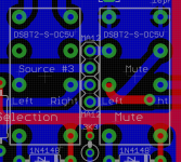
You have access to the un-attenuated and the attenuated audio-signals as shown in the image below.
As I understand you, you want to bypass the attenuation and feed the signal directly to your AMP, in case you select "Home Theatre" as source.
I will not offer this feature on the standard VCPre-PCB for these 2 reasons:
- it is very (!) hard to insert an additional relay on current VCPre-PCB version
- I (myself) do not like to put another strain / load (relay) on the audio-signal
But I will offer you an additional PCB that will fulfill your needs:
Being driven from the VCPre-PCB, this small enhancement will let you switch between attenuated and non-attenuated audio signals.
I hope that this solution will suit you.
Best regards - Rudi_Ratlos
I am not a "multimedia-man"
!You have access to the un-attenuated and the attenuated audio-signals as shown in the image below.
As I understand you, you want to bypass the attenuation and feed the signal directly to your AMP, in case you select "Home Theatre" as source.
I will not offer this feature on the standard VCPre-PCB for these 2 reasons:
- it is very (!) hard to insert an additional relay on current VCPre-PCB version
- I (myself) do not like to put another strain / load (relay) on the audio-signal
But I will offer you an additional PCB that will fulfill your needs:
Being driven from the VCPre-PCB, this small enhancement will let you switch between attenuated and non-attenuated audio signals.
I hope that this solution will suit you.
Best regards - Rudi_Ratlos
Attachments
Last edited:
Goldkenn, Bill: I have added two 2-pole connectors in front of the mute-relay.
Does it suit you?
Best regards - Rudi_Ratlos
It seems great!
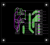
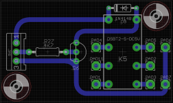
@Wineds, Wirehead.be: find attached the current layout of the VCPre - PCB.
I put the HTBypass-connector on the bottom right side.
It has 3 pins: VCC, GND and a µProcessor output-pin that will connect to the small HTBypass-PCB.
Best regards - Rudi_Ratlos
I put the HTBypass-connector on the bottom right side.
It has 3 pins: VCC, GND and a µProcessor output-pin that will connect to the small HTBypass-PCB.
Best regards - Rudi_Ratlos
Attachments
I am also interested
Hi Rudi,
I am interested in this project if ever convert to group buy, I will participate. Thanks for your great work.
Regards,
Jorge
Gentlemen,
my DIY-friend METAL and I have been working for quite a while on a passive pre-amp that shall be versatile (give us all the functionality
that we need) and comfortable, so we can sit in our armchair and control everything per remote-control-unit.
This is the current result of our project:
http://abload.de/img/display012a0xwe.jpg
This PCB (I call it VCPre hereafter) has the following functionality:
- Source selection of up to 3 input sources
- Mute function
- Attenuation, either based on a LDR - solution or a traditional AUDIO potentiometer
- Support of motorized potentiometers
- Display of attenuation
- Display of current temperature of your heatsinks
- Implementation of a Standby / Resume-from-Standby function for your amplifier
- Status-display on a 1x16chars LCD module
- Every function can be controlled by an infrared remote-control unit
The functionality of the VCPre is accomplished by the use of a PIC 16F886 µProcessor.
I myself am using the current VCPre PCB-version in the build of my FC-100 amplifier, it works flawlessly, and I did not yet receive any complaint
from any of the German DIYers, who have already installed the PCB.
http://abload.de/img/neverbeforehavelisten5hzwb.jpg
If there is some interest, I will start a group-buy offering the PCB(s), documentation, pre-programmed µProcessor, hard-to-get components (if any), ...
Best regards - Rudi_Ratlos
Hi Rudi,
I am interested in this project if ever convert to group buy, I will participate. Thanks for your great work.
Regards,
Jorge
- Status
- This old topic is closed. If you want to reopen this topic, contact a moderator using the "Report Post" button.
- Home
- Group Buys
- Versatile and comfortable passive pre-amp