... BOM and schematic sometime later in the week.
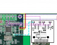
Given I'm electronics challenged, I'd very much appreciate you confirming the connections to the BIIISE if possible. This is what I was thinking, see below
Also I assume it needs a separate 3.3v supply (although it seems to have 2 * 3.3v inputs
 ) does anyone know the best way to do this can it be taken from the BIIISE?
Attachments
Last edited:
BIIISE
If you are planning to use a BIII/BIIISE DAC with the AKL re-clocker, please note that there appears to be some sort of re-clocker already on board the BIII. Not sure what those chips are (or if they can be disabled/bypassed) but any benefit of the PotatoChips on the AKL unit is negated by the ones on the BIII. You may be better of taking the outputs from the isolator only and connect these to the BIII inputs.
Also, if you not using the on-board LDO of the AKL (not shown in the preview) then both the 3.3V inputs need to be connected to a suitable 3.3V external supply-just the way the PotChip package is.
Last edited:
BIII support
... Awaiting more clarification.
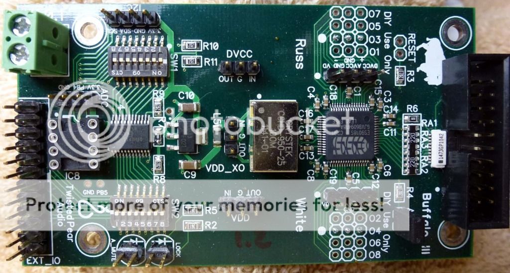
TPA site indicate "Integrated Re-Clocker on board" and there are ICs (U4 .. U5) that look like Flip-flops. Other think they are not but for DSD/PCM switching.
Any clearer pic on U4-U5 area would help. Sorry, I do not have any Buffs myself, they wouldn't even sell me one!
Other than that the connections are correct. 'MCLK' from AKL doing another 're-clocking' on the BIII needs further investigtion.
No similar issues with BIIs or DACs without re-clockers built-in.
3.3V supplies can be taken from DAC DVCC but if you do not wish to disturb the DAC supplies then get a separate 3.3V source for the AKL board.
More App notes are on the way to help further ....
... Awaiting more clarification.
TPA site indicate "Integrated Re-Clocker on board" and there are ICs (U4 .. U5) that look like Flip-flops. Other think they are not but for DSD/PCM switching.
Any clearer pic on U4-U5 area would help. Sorry, I do not have any Buffs myself, they wouldn't even sell me one!
Other than that the connections are correct. 'MCLK' from AKL doing another 're-clocking' on the BIII needs further investigtion.
No similar issues with BIIs or DACs without re-clockers built-in.
3.3V supplies can be taken from DAC DVCC but if you do not wish to disturb the DAC supplies then get a separate 3.3V source for the AKL board.
More App notes are on the way to help further ....
BIII support
Ok thanks, BIII for the version shown earlier is fine, just direct connections to the DAC. You will get the full benefits of the AKL re-clocker.
So it is BIIISE then, this must be their latest release. IC4-IC5 on this version looks like single D-FFs to me and there is a mention of "Integrated Re-Clocker"
Last edited:
......
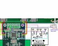
Snag the clock there?
Yes, and use it to drive the RCK input of the Re-clocker board
.....
So it is BIIISE then, this must be their latest release. IC4-IC5 on this version looks like single D-FFs .....
Possibly they are bus switches?
Yes, and use it to drive the RCK input of the Re-clocker board
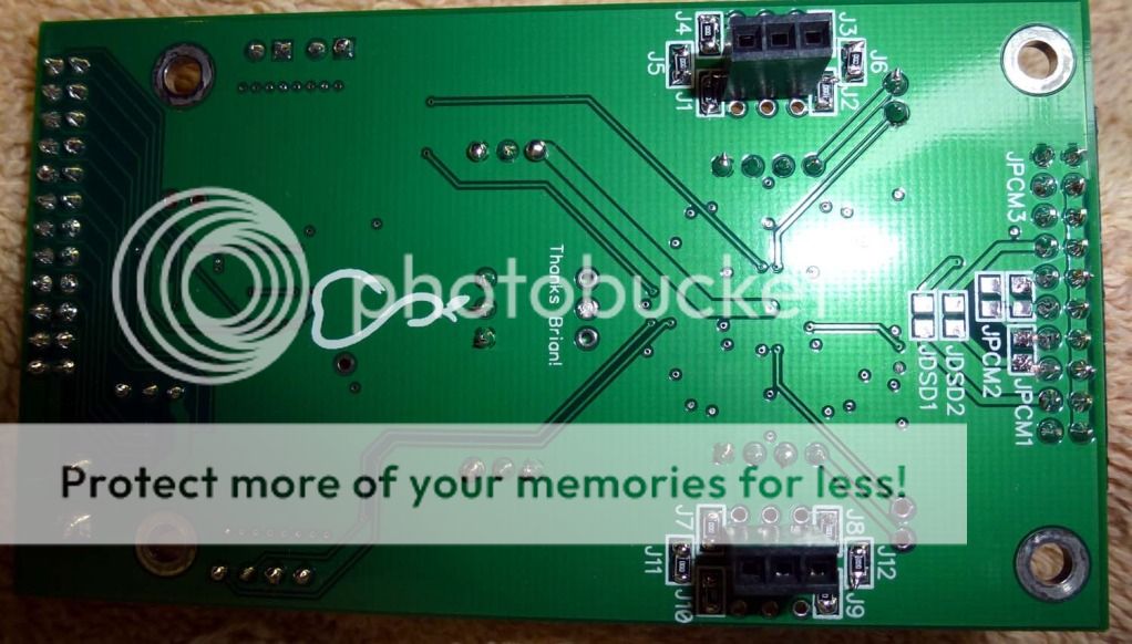
Thanks Acko. Looking at bottom of board do you think one could solder a U.Fl connector to the bottom or not enough contact for any strain on cable?
Also, with dual mono, should you connect to the master board clock? (I'm guessing yes but don't really know).
Last edited:
You can try this to secure a U.FL connector this way. Alternatively, cut off one end of the u.fl cable assembly, strip a short length to get the leads and dovetail connection to the pin pads.Thanks Acko. Looking at bottom of board do you think one could solder a U.Fl connector to the bottom or not enough contact for any strain on cable?
Also, with dual mono, should you connect to the master board clock? (I'm guessing yes but don't really know).
Yes, this should be fine. How are the signals connections to reclocker then?
BIII SE
IC4-IC5 looking more like bus switches now with 'IP_S' controlling them. I am guessing here but they could be used to switch between Spdif and I2S i.e. preventing 'BCK' from interfering with Spdif lock. Previous versions use this 'SideCar' thing but now on-board? But then again where is this "Integrated Re-Clocker" as mentioned on their site
So it is BIIISE then, ..... IC4-IC5 on this version looks like single D-FFs to me and there is a mention of "Integrated Re-Clocker"
Possibly they are bus switches?
IC4-IC5 looking more like bus switches now with 'IP_S' controlling them. I am guessing here but they could be used to switch between Spdif and I2S i.e. preventing 'BCK' from interfering with Spdif lock. Previous versions use this 'SideCar' thing but now on-board? But then again where is this "Integrated Re-Clocker" as mentioned on their site
Last edited:
You can try this to secure a U.FL connector this way. Alternatively, cut off one end of the u.fl cable assembly, strip a short length to get the leads and dovetail connection to the pin pads.
I'm good with the coax/leads. Just have to remember its upside down and grab the right one.
Yes, this should be fine. How are the signals connections to reclocker then?
I'd use U.Fl connector/coax. Thanks!
They are switches according to TPA.
http://www.diyaudio.com/forums/twisted-pear/219921-buffalo-iii-se-2.html#post3195426
http://www.diyaudio.com/forums/twisted-pear/219921-buffalo-iii-se-2.html#post3195426
IC4-IC5 looking more like bus switches now with 'IP_S' controlling them. I am guessing here but they could be used to switch between Spdif and I2S i.e. preventing 'BCK' from interfering with Spdif lock. Previous versions use this 'SideCar' thing but now on-board? But then again where is this "Integrated Re-Clocker" as mentioned on their site
The B III SE is like having the 'Sidecar' built in. I only know what I read about it. Not sure if you can learn what you want from the Integration Guide. B III SE starts at page 36.
http://www.twistedpearaudio.com/doc...-Buffalo_III_DAC_Integration_Guide_V2.0.0.pdf
They are switches according to TPA.
http://www.diyaudio.com/forums/twisted-pear/219921-buffalo-iii-se-2.html#post3195426
Many thanks! "SideCar" switches then. Closing in slowly but where is this "Integrated Re-clocker"?
Many thanks! "SideCar" switches then. Closing in slowly but where is this "Integrated Re-clocker"?
It says same for BIII...referring to what goes on with the ESS Sabre chip?
I read this in the white paper...
"a patented technique is used to re-create
the audio data in a crystal-controlled low phase-noise clock
domain completely isolated from the clock domain of the
transport medium and so not at all related to the clock domain
in which the data was sampled. This latter feature ensures that
there is zero jitter transfer from the various interface clocks to
the digital data and that the digital clock of the DAC itself can
be optimized for noise and power consumption.
Finally, operation of the DSP in the transport medium clock domain
(the “Fs” domain in which data is delivered to our DAC) is
done in a “gated clock” mode –a form of serial/parallel
processing that prevents any inter-modulation of operating
current between the DAC clock and the data transport clock
that could cause harmonically related noise on the system
power supplies. The following sections explain these features
in more detail."
Last edited:
BIIISE support
Alright then, must have been technical hyperbole all along and caused confusion.
So I stand corrected. There is no Re-Clocker function on-board the BIIISE (or any of the BUFFs) and so you can use it with the external Re-Clocker (AKL) for full benefits
All connections are correct as you have shown. MCLK of the AKL board can drive the EXT_MCK if the BIIISE XO is disabled (unpowered- as TPA advice).
This assumes the AKL itself if clocked by an external source at RCK inputs (>50MHz). You will get true synchronous operation this way but MCLK output from AKL is 24.576Mhz max as produced by the transport (Amanero) and high fs audio capability may be limited
Alternatively EXT_MCK (100MHz with BIIISE XO powered) from the BIIISE (nice U.FL connector) can drive the RCK inputs of the AKL board. You can go up to 384KHz this way. As the DAC and the Re-clocker are tied to the same clock, some form of synchronous operation could happen but we need to test and see later.
Alright then, must have been technical hyperbole all along and caused confusion.
So I stand corrected. There is no Re-Clocker function on-board the BIIISE (or any of the BUFFs) and so you can use it with the external Re-Clocker (AKL) for full benefits
... confirming the connections to the BIIISE if possible.
All connections are correct as you have shown. MCLK of the AKL board can drive the EXT_MCK if the BIIISE XO is disabled (unpowered- as TPA advice).
This assumes the AKL itself if clocked by an external source at RCK inputs (>50MHz). You will get true synchronous operation this way but MCLK output from AKL is 24.576Mhz max as produced by the transport (Amanero) and high fs audio capability may be limited
Alternatively EXT_MCK (100MHz with BIIISE XO powered) from the BIIISE (nice U.FL connector) can drive the RCK inputs of the AKL board. You can go up to 384KHz this way. As the DAC and the Re-clocker are tied to the same clock, some form of synchronous operation could happen but we need to test and see later.
Last edited:
Alright then, must have been technical hyperbole all along and caused confusion.
So I stand corrected. There is no Re-Clocker function on-board the BIIISE (or any of the BUFFs) and so you can use it with the external Re-Clocker (AKL) for full benefits
All connections are correct as you have shown. MCLK of the AKL board can drive the EXT_MCK if the BIIISE XO is disabled (unpowered- as TPA advice).
This assumes the AKL itself if clocked by an external source at RCK inputs (>50MHz). You will get true synchronous operation this way but MCLK output from AKL is 24.576Mhz max as produced by the transport (Amanero) and high fs audio capability may be limited
Alternatively EXT_MCK (100MHz with BIIISE XO powered) from the BIIISE (nice U.FL connector) can drive the RCK inputs of the AKL board. You can go up to 384KHz this way. As the DAC and the Re-clocker are tied to the same clock, some form of synchronous operation could happen but we need to test and see later.
Like this ?
PS: Thanks for your tireless work on this issue.
Attachments
Like this ?
PS: Thanks for your tireless work on this issue.
Yes, all ready to go! No problems
- Status
- This old topic is closed. If you want to reopen this topic, contact a moderator using the "Report Post" button.
- Home
- Group Buys
- Amanero Isolator/Reclocker GB