Hey acko
What's the best way to connect a BBb to your AKU384?
If you are asking about the actual connections, post #1179 might help.
I have checked the details and a matching interface board with Flex cable connections does not look too difficult. Will roll out with U.FL connectors and 0.1" headers. Connect straight to DACs or via the S03 board
Hi Acko
With an interface board, is there a suitable male ffl connector so that the board could plug straight into a female ffl connector, eliminating a cable run?
In the absence of any standard for which 'pin' serves which data connection it will be specific to the Edel board if you try to use ufl connectors; better to just bring the pins out to a normal pin connection arrangement to be more flexible. If there were standards you coud equip the SO3 board with an ffl connector.
Ray
With an interface board, is there a suitable male FFC connector so that the board could plug straight into a female FFC connector, eliminating a cable run?
Something like this?
XF2M24151A - OMRON ELECTRONIC COMPONENTS - CONNECTOR, FFC/FPC, SMT, ZIF, | Farnell UK
Ray
Last edited:
Something like this?
XF2M24151A - OMRON ELECTRONIC COMPONENTS - CONNECTOR, FFC/FPC, SMT, ZIF, | Farnell UK
Ray
Yes, these are readily available including the cables so all good to go with the adapter board
Also mulling about adding this type of connector onto the next revision of the S03 board. This will make the interconnects neat and simple- easy as... Thoughts?
Last edited:
Yes, these are readily available including the cables so all good to go with the adapter board
Also mulling about adding this type of connector onto the next revision of the S03 board. This will make the interconnects neat and simple- easy as... Thoughts?
Acko, I considered suggesting modifying the SO3 with an FFC connector but abandoned it for the same reason as I don't think the ufl option on the adaptor board will work - the mapping of the pins to make the right connections. If you map the pins for, say, the Edel NMR board outputs they probably won't be correct for different boards should some come along. Of course, if you're only aiming to connect the Edel NMR then it will be possible to use ufl connectors on an adaptor or an FFC socket on a modded SO3.
If you go the adaptor board route I would personally prefer to have it with a male FFC connector (like the one I linked to?) mapped to a 0.1in matrix pin-out header (with just the required number of pins). It would plug into the female FFC socket as a small daughter board so you only need the one set of hook-up wires. Make the pin-out header a DIY option so you could solder the hook-up wires to the PCB pads if you want.
Ray
Last edited:
Any idea on this guys?dwjames said:I'm back to diagnosing my s03 build, but now I have 3.3v at pin 4 of my X1 and 3.03v on pin 3, which is double what it was last time I checked it. Does this mean I've bust it?
I've identified I had some dodgy power and gnd connections to U3 and fixed those now, could this have caused an issue?
thanks,
James
I'm back to diagnosing my s03 build, but now I have 3.3v at pin 4 of my X1 and 3.03v on pin 3, which is double what it was last time I checked it. Does this mean I've bust it?
I've identified I had some dodgy power and gnd connections to U3 and fixed those now, could this have caused an issue?
thanks,
James
Any idea on this guys?
I am afraid this is not good. You may have to change both the Clock and U3!
Last edited:
"SuperCape" for BBB
Yes, this is in the works. The concept (as posted earlier) had lain fallow for while to get more ideas but I have now got all the bits and pieces to roll out a board. Yes, it will match the BoticOS interface for I2S/DSD. No plans for a GB as yet. More of build and supply for those who are interested.
Btw, rumour says Acko might coming out a "SuperCape" for BBB! This SuperCape also has UPS with lithium upto 1hr after power shortages, and also has all the I2S/DSD switching capability like the Botic Cape? If the Rumor is true, I definitely be interested and put my name down for it. May be Acko could clarify this Rumor for group buying?
Best,
Chanh
Yes, this is in the works. The concept (as posted earlier) had lain fallow for while to get more ideas but I have now got all the bits and pieces to roll out a board. Yes, it will match the BoticOS interface for I2S/DSD. No plans for a GB as yet. More of build and supply for those who are interested.
A quick preview of an add-on board for BBB that supports UPS
1. UPS kicks in when external power is removed. On-board PWR_MON will continue to power the BBB (~1hr) or options to safely shutdown BBB immediately. Same shutdown action if battery level goes below operational level
2. Automatic boot from SDCARD or internal Flash. No boot button press required.
3. Matching U.FL interfaces and PWR/CKSEL to the S03.
The above features will practically result in a reliable 'hands-free' system that can be tucked away
Last edited:
AKU384 is based on Amanero core and Linux compatible. You should be able to connect directly to USB port of BBB and use Volumio, RuneAudio etc
Thanks mate.
I'll get a bbb and see how it compares to my pc
.....
If you go the adaptor board route I would personally prefer to have it with a male FFC connector (like the one I linked to?) mapped to a 0.1in matrix pin-out header (with just the required number of pins). It would plug into the female FFC socket as a small daughter board so you only need the one set of hook-up wires. Make the pin-out header a DIY option so you could solder the hook-up wires to the PCB pads if you want.
Ray
This looks great!
Will roll out accordingly
If you go the adaptor board route I would personally prefer to have it with a male FFC connector (like the one I linked to?) mapped to a 0.1in matrix pin-out header (with just the required number of pins). It would plug into the female FFC socket as a small daughter board so you only need the one set of hook-up wires. Make the pin-out header a DIY option so you could solder the hook-up wires to the PCB pads if you want.
Just some further thoughts...
My comment 'with just the required number of pins' is confusing. For a 24way FFC connector there will be 24 header pin pads to facilitate different connection mapping possibilities.
There seem to be different patterns of 24 way FFC connectors and I wouldn't assume the male one I linked to is the right one! I found it with a very quick search.
The FFC connectors I looked at are all, unsurprisingly, smd. Leaving aside my own inadequacies with DIY smd soldering, I'm not sure that the pads will be accessible enough for DIY or were you planning on a pre-mounted connector?
Ray
Thanks.I am afraid this is not good. You may have to change both the Clock and U3!
I guess I'll pull the clock chip off and see if it gives 1.65v ish when tested on its own and go from there... Are the u3 potato semi chips still available on eBay? I had a quick search but couldn't find them.
Just some further thoughts...
My comment 'with just the required number of pins' is confusing. For a 24way FFC connector there will be 24 header pin pads to facilitate different connection mapping possibilities.
There seem to be different patterns of 24 way FFC connectors and I wouldn't assume the male one I linked to is the right one! I found it with a very quick search.
The FFC connectors I looked at are all, unsurprisingly, smd. Leaving aside my own inadequacies with DIY smd soldering, I'm not sure that the pads will be accessible enough for DIY or were you planning on a pre-mounted connector?
Ray
Will sort out the details later.
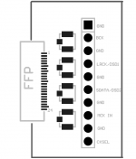
See preview of this daughter board.
All smd parts mounted
Attachments
Last edited:
Ahh yes, with u3 removed, that will tell me if the clock is damaged or not. I only need to remove it if it's broken and if it's broken, I don't need to be quite so careful with itCan be a bit messy. There is something from ChipQuik that could help. Google for videos.
I would think remove U3 first and test the Clock
")
Thanks
Will sort out the details later.
See preview of this daughter board.
All smd parts mounted
Looks good Acko. You're going the Edel specific route then? That suits me.
Ray
Looks good Acko. You're going the Edel specific route then? That suits me.
Ray
If you meant the S03 board variant then, no. Will keep S03 unchanged for the time being since the adapter takes care of the pinouts to match
If you meant the S03 board variant then, no. Will keep S03 unchanged for the time being since the adapter takes care of the pinouts to match
No, I meant the adaptor board is only going to map the pin outs of the FFC connector on an Edel NMR board? No need to modify the SO3 in that case.
Ray
- Status
- This old topic is closed. If you want to reopen this topic, contact a moderator using the "Report Post" button.
- Home
- Group Buys
- Amanero Isolator/Reclocker GB