by lowest .... meaning lowest, or No Bandwidth?
Let's aim for the lowest BW first. There are reports of "No BW" taking DAC performance level even higher but this might require even tighter integration...
"Ability to adjust the delays"
Do you know that he actually does this ?
From the looks of it the output MCLK needs to be delayed to match and as I proposed earlier to adjust R1/R2 of the S03 board to suit.
Not sure how this could be done on the Si570? Possibly further processing of the output clock?
Yes, delays are the bane of any system

Needs further investigation ...
Last edited:
@ deanoUK: no I dont know for sure he does do that, but I do know that the si570 board seemed to go through even more revisions than the fifo itself. the changes included several different layouts for the FF, several different types and makes of FF, several different power supplies. the first one to make it into the wild was V3 I think and final version is 3.5, he starts at 0.1 afaik … then there is the software/firmware revisions. there is also much cleaner connections, impedance and layout on fifo vs amanero
@ Acko: I wasnt suggesting trying no BW, just clarifying what both you and Dean meant, since certainly having it on the no BW setting could explain the issues tbh i'm not even sure if its possible, I have read very vague and somewhat fanciful stories of it, but it would seem very difficult, if not impossible to achieve.
@ Acko: I wasnt suggesting trying no BW, just clarifying what both you and Dean meant, since certainly having it on the no BW setting could explain the issues
tbh i'm not even sure if its possible, I have read very vague and somewhat fanciful stories of it, but it would seem very difficult, if not impossible to achieve.@ deanoUK: no I dont know for sure he does do that, but I do know that the si570 board seemed to go through even more revisions than the fifo itself. the changes included several different layouts for the FF, several different types and makes of FF, several different power supplies. the first one to make it into the wild was V3 I think and final version is 3.5, he starts at 0.1 afaik … then there is the software/firmware revisions. there is also much cleaner connections, impedance and layout on fifo vs amanero
I'm reasonably certain that Ian does not do delays in the CPLD, my reasoning is that all firmware revisions predate the introduction of the Si570. Most of the FIFO is best treated as a black box because Ian does have some proprietary protocols that do some nice things in the background that he doesn't make public for obvious reasons.
Last edited:
I repeat (again), i'm not really even making the claim, just saying its possible and there are numerous opportunities to do it in software and layout/hardware through the many revisions. that being said, i'm not sure I follow your reasoning though, Ian was playing around with si570 for ages before the last revision, as you well know he is known for putting 'easter eggs' in his designs. why it would need to be something done in the CLPD, or something that relates to the si570 alone i'm not sure ...
Last edited:
Ians's Isolator/Si590 full sync with Amanero
Just a quick one whilst still waiting for parts for the SO3.
![IMG_0902[1].jpg](https://www.diyaudio.com/community/data/attachments/348/348202-abdea0ad4a23c8c70d04076e0f3a38e2.jpg "IMG_0902[1].jpg")
Ians's Isolator/Si590 full sync with Amanero.
MCK=98.3040 - 384kHz No clicks or pops at LOW, LST=Just noise.
MCK=90.3168 - DAC lock light on, no audio (need to look at Arduino software).
Si590 board divides MCK by 2 before sending back to FIFO/Amanero.
Just a quick one whilst still waiting for parts for the SO3.
Ians's Isolator/Si590 full sync with Amanero.
MCK=98.3040 - 384kHz No clicks or pops at LOW, LST=Just noise.
MCK=90.3168 - DAC lock light on, no audio (need to look at Arduino software).
Si590 board divides MCK by 2 before sending back to FIFO/Amanero.
Last edited:
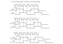
S03 Board Timing 384KHz @ 98.304MHz
A quick analysis of the SO3 board timing with delays d1, d2 and a massively delayed d3 revels no issues with the data integrity. MCLK locks onto signal quickly and from there on everything is in step and aligned!
A quick analysis of the SO3 board timing with delays d1, d2 and a massively delayed d3 revels no issues with the data integrity. MCLK locks onto signal quickly and from there on everything is in step and aligned!
Attachments
Last edited:
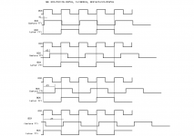
Timing for 49.152MHz/384KHz
A quick analysis of the SO3 board timing with delays d1, d2 and a massively delayed d3 revels no issues with the data integrity. MCLK locks onto signal quickly and from there on everything is in step and aligned!
Attachments
Agreed.
So its as if the 10nS delays from the isolators where designed for the job !
There is also the output skew to take into account, but the timing still works.
I am now thinking that the Amanero does not handle the 90/98 clocks well.
The Amanero clock input (originally an output) has a series resistor. Will try linking this out.
Should have the S03 assemble in a few hours. So can try /4 MCK input.
Last edited:

Finished assembling the SO3 a few hours ago, then had a few problems with the clock select.
Using the Amanero maintenance tool version 1.15 it should be possible to configure Pin 11 as clock select output.
This does not work. Pin 11 remains as the MUTE output.
Configuring Pin 1 as clock select works. Doing this inverts the clock select logic for the SO3.
To implement Pin 1 clock select on the SO3 you need to,
on the 20 pin Amanero connector -
a) Do not mount the 20 pin connector yet, you can not get to the track once it is mounted.
b) Cut track connected to Pin 11.
c) Run a wire from Pin 1 to the via that runs to the IL172.
d) Swap X1 and X2.
I then had strange a problem with my Fox Expresso oscillators.
They would not go high impedance on the output, regardless of the status of the output enable pin.
So I am currently only using a 98.304 Mhz oscillator.
My order for the Potato chips and Si clocks seems to have disappeared mid Atlantic so I have used the following UK available replacements.
Potato Replacment
PO74G74ATEXAS TEXAS SN74LVC74ADRG4
PO74G38072A IDT ICS8304AMILF (need to lift pins 5 and 8).
The replacement parts do not have as good a spec as the Potato/Si ones.
I will be still be building my second SO3 with the Potato/Si parts.
So far without adjusting output resistor values it locks to my BIIIse set to “LST” playing 384kHz material.
Turning off DPLL - plays for a short period then low level audio and loud hiss.
More tweaking later.
By the way it SOUNDS GOOD.
Well done acko.

Very impressed by your troubleshooting skills!
Thanks.
Beers all round
Deano, thanks for all your testing and observations.
I've just got all the components together, including the Si590s and PotSemi parts (sorry, I only have 1 each PO74G74A and PO74G38072A spare, hope I don't need them!.) for the SO3 and an AKD16.
Now I'm wondering whether to mount the Si590s until the anomalies are sorted.
I've just got all the components together, including the Si590s and PotSemi parts (sorry, I only have 1 each PO74G74A and PO74G38072A spare, hope I don't need them!.) for the SO3 and an AKD16.
Now I'm wondering whether to mount the Si590s until the anomalies are sorted.
Deano, thanks for all your testing and observations.
I've just got all the components together, including the Si590s and PotSemi parts (sorry, I only have 1 each PO74G74A and PO74G38072A spare, hope I don't need them!.) for the SO3 and an AKD16.
Now I'm wondering whether to mount the Si590s until the anomalies are sorted.
As we know only Amanero can provide a definitive answer to future firmware.
However -
Using Pin 1 for clock select you lose the USB plugged signal -
Not sure how useful this is as your player software will soon know if the
Amanero has gone missing.
Using Pin 11 for clock select you retain the MUTE signal, this may come in handy,
I have no idea why the Fox Expresso oscillators will not switch to high impedance output. I have asked Fox and await a reply.
On the DIYINHK XMOS to I2S board the output of two Fox Expresso oscillators are tied together.
Must have the only pair on the planet the refuse to go Hi Z.
Other designs I have seen use a separate clock fan out buffer for each oscillator, enable/disable is implemented on the clock buffer not the oscillator.
Last edited:
this guy Domenico is unbelievable, I have never seen such good feedback between seller-customer, he did solve every problem and kept his every single promise about the Amanero product including the ASIO driver back then
if every single seller would behave the same way ...
if every single seller would behave the same way ...
So, when Domenico alters the firmware we can use pin11 for XO selection. It would be very nice to move the clock to pin 7 also. This way we don't have to cut or rewire anything.
There are two pins for XO selection (1 and 11) not just one, one to enable 44.1K based XOs and another for 48K based. Pin 7 has never been for clock, it has always been DSD_OE which is necessary for many DAC implementations.
There are two pins for XO selection (1 and 11) not just one, one to enable 44.1K based XOs and another for 48K based. Pin 7 has never been for clock, it has always been DSD_OE which is necessary for many DAC implementations.
Agreed!
There are two pins for XO selection (1 and 11) not just one, one to enable 44.1K based XOs and another for 48K based. Pin 7 has never been for clock, it has always been DSD_OE which is necessary for many DAC implementations.
Ok, I understand about DSD_OE signal. But we need to rewire only one pin to select XO, transistor inverts enable signal for the other. Of course, we could utilize both pins to their respective XOs, but we are 1 isolator channel short, at least on the PCB.
For power supply, I will try with just one +5V with on board regulators and later will split them if nececary or beneficial. Amanero will have dedicated (other transformer) power supply.
- Status
- This old topic is closed. If you want to reopen this topic, contact a moderator using the "Report Post" button.
- Home
- Group Buys
- Amanero Isolator/Reclocker GB