
Closing eyes is more exciting
Stooping a bit to the side with your shoulders close to your ears also helps some times
I just finished dry fitting the parts.
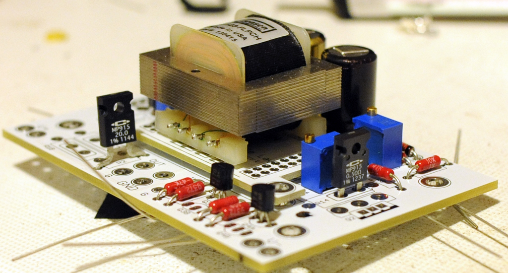
It seems that R13 and R14 are 0.5R caddocks (for IRFs), R2 is a 20R Caddock, a 9.1V zener for the led reference.
Are these correct? Also, what is the polarity mark on the Jensens? Or should I just align the letters and then the dot on the boards?
I m also a bit concerned about the zener polarity. Do they look ok?
Also about the FE, with 10mA jfets, I guess we only populate Q3A qnd Q4A right?
I also do not have an R1. Justin did you forget that one or it would not be included in the GB?
Thanks again for a nice package.
Attachments
Hi all
got the parts thanks Buzz!!
few questions
I,m building the f6 buffered using the original schematic on the firstwatt site
and I need to clarify a few things
1, the f6 buffered schematic above does not have r11/12 I suspect these are for jft degeneration ,do I use them ? if so what goes there (I have 4 x 10r left from buzz,s kit after populating everything as per the above schematic )
2, what way do the led install ,one of the solder pads is square the other is round(teas boards)
3, what are the diodes for in the kit ,the f6 buffered schematic does not show any
4, do I have to install p3 /p4, I just want to build as per nelsons original circuit which does not use these
rgds Sheafer
Could you take a closer pic of those zeners,couse I got a resistor there instead,or maybee that will work as well?It seems that R13 and R14 are 0.5R caddocks (for IRFs), R2 is a 20R Caddock, a 9.1V zener for the led reference.
The Zener's were included for those folks who would be using the IRF outputs. It give you a larger voltage to divide down with the pot for the gate of the mosfet.
The Led's have one long leg. That leg is the anode of the LED.
You will have to post the schematic you are talking about for me to know how to advise. There were several put out in the article
The Led's have one long leg. That leg is the anode of the LED.
You will have to post the schematic you are talking about for me to know how to advise. There were several put out in the article
- Status
- This old topic is closed. If you want to reopen this topic, contact a moderator using the "Report Post" button.
- Home
- Group Buys
- GB for F6 Convertible Clone boards