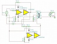
Here's the mixed feedback driver circuit for the CineMag transformer. I used a 10k ohm load instead of the 1k shown. Predicted performance is 2nd harmonic at -90 dB @ 20Hz, which is about what I got in reality. Without the circuit, 20Hz performance is horrible. Predicted performance for 1kHz is to have the 2nd harmonic at about -129dB. So, this is about as good as it gets for an output transformer, as far as I know. Noise is extremely low.
I have since modified this circuit to include a LME49710 unity gain buffer in front since the input impedance for this circuit is only 1k ohm.
I realized that I really do need to have balanced sources and measuring instruments because I have some balanced gear and I wouldn't be able to test it otherwise.
So, I think I'll try the cross feed circuit in real life and see if it blows up, oscillates, or latches. Several manufacturers use the cross feed circuit in their balanced line drivers, but they only have performance at -100dB or thereabouts. I'm hoping to be much better than that.
I suppose I could have one single ended output and one balanced one, and use a simple circuit like you have shown for the balanced one. That way it's unlikely that one of the hot pins on the balanced circuit will be grounded by a single ended circuit.
Thanks for your suggestions!
Attachments
Interesting,
How will your circuit perform with single drive and series connected primaries (N2, N3)?
The circuit is derived from a Lundahl app note:
http://www.lundahl.se/pdfovrigt/feedbck.pdf
which in turn references a German patent from a while ago.
Walt Jung has tried out the circuit as well with good results.
The two independent primaries are required for the circuit to function as intended. I have not tried deleting the positive feedback and driving it as you suggest.
Hi,
Yes, I've seen the app note. I thought of the possibility to eliminate 1/2 of the electronics and run as the Lundahl unbalanced example.
Yes, that will work, but the distortion will be a little higher. Mr. Jung tried both of them and found the balanced version had lower THD.
Ok, Mr Jung certainly know. Do you have a link to this material that one can digest?
Thanks for fueling interest.
Btw, I went to my storage looking for line transformers that I remember spotting at one time looking for something else. The same thing happens again. I found no less than 3 small ready made unbalanced - balanced converter PCB's with symmetry trimmers. Just have to put in fancy OP-amps. Now I must look for something else so I can find the transformers.")
Thanks for fueling interest.
Btw, I went to my storage looking for line transformers that I remember spotting at one time looking for something else. The same thing happens again. I found no less than 3 small ready made unbalanced - balanced converter PCB's with symmetry trimmers. Just have to put in fancy OP-amps. Now I must look for something else so I can find the transformers.
Ok, Mr Jung certainly know. Do you have a link to this material that one can digest?
Thanks for fueling interest.
Btw, I went to my storage looking for line transformers that I remember spotting at one time looking for something else. The same thing happens again. I found no less than 3 small ready made unbalanced - balanced converter PCB's with symmetry trimmers. Just have to put in fancy OP-amps. Now I must look for something else so I can find the transformers.
http://waltjung.org/PDFs/ADI_2002_Seminar_Ch6_Audio_Drivers_I.pdf
Discussion starts on page 6.69.
I am surprised because the balanced version of this circuit does in fact use a single primary. I had forgotten about that completely.
Good document, certainly something to read in detail.
Thinking loud, in your circuit you monitor just one winding while providing current to both windings (one has that sense resistor). This made me thinking enough to ask what i did.
I think the idea is that the positive feedback correction is applied to the first opamp, and the second one already receives the corrected signal, so positive feedback isn't required for the second one. I've tried it just now in simulation and while the 20Hz distortion is improved by 10dB, the 1Khz distortion is considerably worse. I don't have a perfect model for the transformer though so who knows. I have not tried the one used by Mr. Jung.
Yes, but if the primaries differ slightly (in real life). Can you get the same performance by taking feedback from just one winding? Me thinks that both windings should be included.
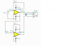
Performance is actually not much better with the Jung circuit shown in the document I cited earlier. This circuit has the 2nd harmonic at only about -97dB down @ 20Hz, 1.4 Vrms output. Transformer has permalloy core, 300 turns, DC resistance of 18 ohms per winding, etc.
Attachments
Last edited:
Have you tried to adjust gain in lower OP-amp as in circuit by Ljung?
Yes, I varied R5 by +/- 100 ohms with much worse THD each way.
While these are probably the best that can be had from a line level output transformer, we're still talking about a second harmonic down about 90dB or so. Since I don't have all of the particulars of the transformer, I have to guess at some of the parameters. The Jung circuit is slightly better than the one I originally used. I'm still twiddling with it.
Last edited:
Yes, I varied R5 by +/- 100 ohms with much worse THD each way.
While these are probably the best that can be had from a line level output transformer, we're still talking about a second harmonic down about 90dB or so. Since I don't have all of the particulars of the transformer, I have to guess at some of the parameters. The Jung circuit is slightly better than the one I originally used. I'm still twiddling with it.
Ok, I hope the distortion creeps down further and further...
.
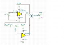
OK, now we are getting somewhere. I guess the devil is in the details. I have the transformer windings in parallel, BTW, just as before. THD is 5x10^-5%, 2nd harmonic is down -130dB from the fundamental @ 20Hz. Performance is just as good @ 1kHz. Adding buffers doesn't really help. So, thanks for the suggestions. Noise is extremely low as well.This one is worth building.
Attachments
Great!
How do different secondary loading influence distortion, any need to reset null?
I don't know. I doubt it matters.
Maybe a misunderstanding, i.e. I wasn't clear? I thought if you had your simulation up and running it would be easy to change transformer secondary load (R6).
I'll be implementing transformer output as well. Really nice to have galvanic separation from the noisy PC ground that jerks around with high frequency.
I'll be implementing transformer output as well. Really nice to have galvanic separation from the noisy PC ground that jerks around with high frequency.
Last edited:
Maybe a misunderstanding, i.e. I wasn't clear? I thought if you had your simulation up and running it would be easy to change transformer secondary load (R6).
I'll be implementing transformer output as well. Really nice to have galvanic separation from the noisy PC ground that jerks around with high frequency.
Oh, I understand you mean the load resistor. It shouldn't matter, but I don't really know.
I recommend a transformer with a high nickel core (80%). They simulate (and in real life perform) much better than anything else.
- Status
- This old topic is closed. If you want to reopen this topic, contact a moderator using the "Report Post" button.
- Home
- Group Buys
- SV Oscillator PCB group buy