Hi Subbu
Nice to read you've shipped V3 Beta PCB to builders.
I may say RC, Realease Candidate, vs Beta.
You say "Sounds pretty good", could you elaborate ?
Did you use Jean Paul LM723 based PSU too ?
I was hoping to read much more from you after such a long time")
From what I've read about V3 DAC, I can say :
1° - V3 DAC uses 0805 & 1210 parts, no smaller 0603 type parts to deal with
2° - 4 ultra low noise LDO (3.3V & 3.6V) as used in improved V2.6
3° - U.FL connectors pads added for I2S input
4° - More left space for non SMD caps alternative : Polymer/Electrolytic/Film
5° - Circuit Design & PCB traces optimized by "Moderator Emeritus" (invaluable input)
6° - SE Version is almost complete, final testing in progress.
Well, the end of waiting is close to ending.
More to come with pics and details, hope it will be soon now
Phil
Nice to read you've shipped V3 Beta PCB to builders.
I may say RC, Realease Candidate, vs Beta.
You say "Sounds pretty good", could you elaborate ?
Did you use Jean Paul LM723 based PSU too ?
I was hoping to read much more from you after such a long time
From what I've read about V3 DAC, I can say :
1° - V3 DAC uses 0805 & 1210 parts, no smaller 0603 type parts to deal with
2° - 4 ultra low noise LDO (3.3V & 3.6V) as used in improved V2.6
3° - U.FL connectors pads added for I2S input
4° - More left space for non SMD caps alternative : Polymer/Electrolytic/Film
5° - Circuit Design & PCB traces optimized by "Moderator Emeritus" (invaluable input)
6° - SE Version is almost complete, final testing in progress.
Well, the end of waiting is close to ending.
More to come with pics and details, hope it will be soon now
Phil
For the v.3 BOM you might consider a different (and possibly better) LDO reg such as this: http://www.ti.com/lit/ds/symlink/lp2985-n.pdf now available in SOT23 P2P compatible package and 3.6V.
Being a low Zout reg (0.3ohm), low ESR caps can be used at its o/p (MLCC vs Tantalum). Noise 30uV (300Hz-50kHz). Slightly worse PSRR, but we can rely on a low noise pre-reg
Being a low Zout reg (0.3ohm), low ESR caps can be used at its o/p (MLCC vs Tantalum). Noise 30uV (300Hz-50kHz). Slightly worse PSRR, but we can rely on a low noise pre-reg
Patience is the key...
This dac is like a good wine - the longer you wait the better it gets ...
And there's also nothing wrong with a good vinegar
TBH I would like to know if any bom has been proposed, as I am on hold for my other parts due to Mouser minimum quantities policy. Will do everything in one go.
Plus I am getting JG Filter buffer, has anyone tried it with 9023 and directly into amp via pot or something similar, bypassing passive or active amp all together..?
Plus I am getting JG Filter buffer, has anyone tried it with 9023 and directly into amp via pot or something similar, bypassing passive or active amp all together..?
Plus I am getting JG Filter buffer, has anyone tried it with 9023 and directly into amp via pot or something similar, bypassing passive or active amp all together..?
I asked myself the same thing. I assume the 9023 can drive a 20k to 100k pot, so it would probably make sense to put the JG-buffer behind the pot. It will present a low impedance source to the poweramp then.
I am really interested in the setups all you are going to bild with it.
Especially the device between the source and the Subbu v3 DAC would be interesting.
I am looking to build USB DAC with a WaveIO XMOS Based USB->SPDIF/I²S and this Subbu DAC v3... I think this will be a really good setup!
Greetings from Germany!
Ron
Especially the device between the source and the Subbu v3 DAC would be interesting.
I am looking to build USB DAC with a WaveIO XMOS Based USB->SPDIF/I²S and this Subbu DAC v3... I think this will be a really good setup!
Greetings from Germany!
Ron
It wouldn't be that hard to do. Here's what I suggest. I've attached a schematic for the JG filter. In the schematic, you see R1 = 18.9K in the latest version. One could use a 20K volume control and put a 340K resistor in parallel with the pot, which gives ~18.9K resistance. Then hook up R2 to the wiper of the volume control and you have now integrated a volume control into the filter/buffer.I asked myself the same thing. I assume the 9023 can drive a 20k to 100k pot, so it would probably make sense to put the JG-buffer behind the pot. It will present a low impedance source to the poweramp then.
---Gary
Attachments
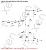
It wouldn't be that hard to do. Here's what I suggest. I've attached a schematic for the JG filter. In the schematic, you see R1 = 18.9K in the latest version. One could use a 20K volume control and put a 340K resistor in parallel with the pot, which gives ~18.9K resistance. Then hook up R2 to the wiper of the volume control and you have now integrated a volume control into the filter/buffer.
---Gary
I´m not sure that is that easy. At the time I wrote about the pot before the buffer, I thought "buffer" = "high input impedance/low output impedance" without looking at the schematic. But here the LC input filter seems indeed to be tailored for a specific application.
Replacing R1 with a pot+parallel R, will change the shunt R/series R in the schematic a lot, depending on the pot position.
Replacing R1 with a pot+parallel R, will change the shunt R/series R in the schematic a lot, depending on the pot position.
I think it actually does work. The suggestion I made loads the pot with the high impedance node of the buffer part of the circuit, so the filter works just fine. The pot becomes the load for the L-R filter and it's value doesn't change because the impedance of the buffer is high. Putting the volume pot on the other side of the inductor, i.e. between the DAC and filter/buffer board would not work.
---Gary
- Status
- This old topic is closed. If you want to reopen this topic, contact a moderator using the "Report Post" button.
- Home
- Group Buys
- ES9023 / WM8804 S/PDIF "Subbu DAC V3" GB Interest