Yep. Its more apparent on some tracks than others. Listening for short bursts back and forth also makes it hard to pick up the differences. Listen for a few minutes though and every time you're switching back to the buffer.
Now I have to make the dac and filter into a new chassis, the plank-of-wood chassis ain't gonna work with mains voltages to the Tx!
Fran
Now I have to make the dac and filter into a new chassis, the plank-of-wood chassis ain't gonna work with mains voltages to the Tx!
Fran
I built a shunt to run my filter - but I'm curious: what is everyone else using?
Fran
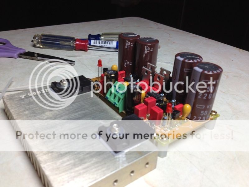
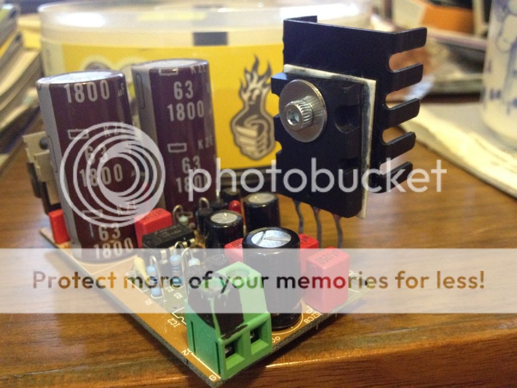
I am using this super reg to power the buffer.

Not a bit overkilled for consumption of less than 20mA ?
Patrick
That was for driving the op-amp IV originally and just handly to use it for the JG buffer.
I am using this super reg to power the buffer.

I also have one of those lying around. Does that regulator really need such a big heatsink?
Regards
I also have one of those lying around. Does that regulator really need such a big heatsink?
Regards
Not really, may be sufficient to just use one of this heat sink.

The active circuit is a cascoded JFET follower.
The follower JFET (BF862 upper) is cascoded and see a constant Vds pretty independent of output voltage.
The lower is a cascoded current source.
As such, the circuit has good PSRR.
For my "kitchen radio" (otherwise known as Sisters' Series), I just use 7815 / 7915.
For a slight upgrade a LT1763/LT1964 on 78xx/79xx pin compatible PCBs.
Or the XEN miniature Cap multiplier.

Even if you wish to use a shunt, your CCS current does not need to be more than 35mA.
A boostered TL431 would do.
Patrick
The follower JFET (BF862 upper) is cascoded and see a constant Vds pretty independent of output voltage.
The lower is a cascoded current source.
As such, the circuit has good PSRR.
For my "kitchen radio" (otherwise known as Sisters' Series), I just use 7815 / 7915.
For a slight upgrade a LT1763/LT1964 on 78xx/79xx pin compatible PCBs.
Or the XEN miniature Cap multiplier.
Even if you wish to use a shunt, your CCS current does not need to be more than 35mA.
A boostered TL431 would do.
Patrick
I just realised that the current values quoted in post #469, 470, & 476 were not well defined.
According to our record, the JFETs that Fran has have Idss of around 14mA.
So thet figure of 28mA he was referring to in post #469 was for one PCB, or two single-ended channels.
And I was misled by the phase he used "on each leg".
So the numbers I gave in post#470 and in #476 were for one channel.
Thus, for 2 single-ended channels, or one PCB, the max current consumption can be about 50mA.
If you then choose to use a shunt regulator, the current source should be delivering minimum 60mA.
(Some of you will of course argue that even 55mA is sufficient.)
Sorry for causing any confusion,
Patrick
EUVL - you are 100% correct, that is for 2 channels. 28mA for each polarity.
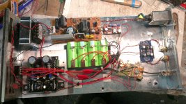
I thought I'd throw up a pic of my almost finished build. I'm using EUVLs 9022 dac (run on batteries) and the filter run from the salas shunt (the old hypnotise B1 boards butchered a bit). The other bits are for charging the batteries.
I had a bad mistake. When I reassembled everything I had no sound and DC offset from the DAC. I fried the 9022 - easier to do than you think with the batteries. After some advice and instructions from EUVL (thanks again!) I managed to remove the dead 9022 and replace it.
All is good, and I can tell you it sounds great with a shigaclone transport.
Fran
Attachments
- Status
- This old topic is closed. If you want to reopen this topic, contact a moderator using the "Report Post" button.
- Home
- Group Buys
- Joachim Gerhard Filter Buffer for ES9022
