That sounds good. The Panasonic TSUP 10000uF caps I shipped are 20mm while the Nichicon KG are 35mm, so either will work. Thanks for the work Tea and CRT. Wonder why there is no 2.2k drain resistor in the F5 T manual for the PSU? Does the bridge/thermistor combo perform that action now?
Will there be room for an RC snubber circuit on the board?
It's worth looking at if it helps with turn on.
I have not seen examples yet of one that will fit the scope of the power supply we are looking for. Any examples of functioning one's for Class A type amps would be helpful for me to look at. I am looking at the Newark Cornell paper which has all the math, but looking for practical implementations.
Yep, across the diodes. There seems to be many values listed, 10-50nF and up to 100 ohms in series. It seems to be a matter of trial and error, experimenting and measuring, and somewhat dependent on the transformer used. I too have read the (cornell?) paper you cited before. I have not seen junction capacitance mentioned on the MUR3020 data sheets. If there was space on the board then people could add the snubbers if they wished.
Sorry that is not as helpful as I had wished,
bk
Sorry that is not as helpful as I had wished,
bk
Anyone want to tell me what brand and model caps they would use on a potential power supply board? CRT wants to make sure the snap in holes punch out right.
Looks like this would be the max voltage, capacitance and size from Panasonic.
ECE-T1JP223FA Panasonic Electronic Components | Mouser
It looks like I want to do 4x 40mm diameter caps for each rail (8 total - but maybe 6 to make smaller). Looks like a 220mm x 90mm or so board. With a V-score break off to mount MUR3020 diodes. It will not really be compact, but should fit into a fairly shallow 12-13 inch chassis with maybe the tranny mounted sideways. Will have LED indicators, C-R-C, with bypass caps, screw down terminal mounts for the wires.
Let me know cap preference. We can make this happen.
Well, since Diyaudio store now has a PSU pcb available, which is pretty much the base line PSU for most NPs' amps, I was thinking of a more "extreme" PSU PCB.
Toecutter's version was something like what I had in mind with 8 caps per rail. One could populate all or some and would end up with endless possibilities in total capacitance based on what caps he preferred/liked. Although I would prefer each rail's CRC resistors to be between the rail's caps resulting in a more narrow and long pcb.
Or be a bit more creative and adaptable with a V-scored section with diodes, a main section with 4 caps per rail and CRC, leds etc and expansion V-scored sections each with 1 cap per rail? So one could stack expansion sections after or before CRC to reach targeted capacitance based on caps chosen. Or in case of different PSU and amp chassis he could also have some caps in the amp chassis away from the main cap bank in the PSU chassis.
Just a thought

...
Any examples of functioning one's for Class A type amps would be helpful for me to look at. I am looking at the Newark Cornell paper which has all the math, but looking for practical implementations.
Here is cviller's implementation of snubbers on his rectfier board (designed for his version of F5):
http://www.diyaudio.com/forums/group-buys/142565-gb-rectifier-boards.html
Photo of board available in post #6 of this thread.
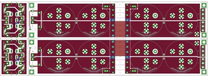
Tentative Power supply Layout
Okay,
Here is a what we got so far for a dual rail supply.
Bleeder and LED in front,
Can put a snubber setup on the diodes.
Can use up to 40mm caps.
The difficult part is getting the snap-in pin configurations from some caps.
I will probably use Panasonics pinout for the non two pin units as a baseline.
Those dont have the direct measurements on the data sheet -making it hard to determine exactness of location. I may have to order a couple to test out.
Any other idea of these type of caps, there measurements etc- let me know.
Anyone want to send me a couple?
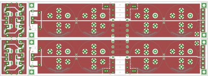
First pic - both layers - next pic top layer, last pic bottom layer.
Looking for feedback.
Okay,
Here is a what we got so far for a dual rail supply.
Bleeder and LED in front,
Can put a snubber setup on the diodes.
Can use up to 40mm caps.
The difficult part is getting the snap-in pin configurations from some caps.
I will probably use Panasonics pinout for the non two pin units as a baseline.
Those dont have the direct measurements on the data sheet -making it hard to determine exactness of location. I may have to order a couple to test out.
Any other idea of these type of caps, there measurements etc- let me know.
Anyone want to send me a couple?
First pic - both layers - next pic top layer, last pic bottom layer.
Looking for feedback.
Attachments
Last edited:
Okay,
Looking for feedback.
It looks great so far!
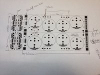
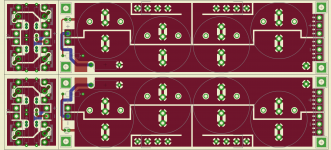
Here is some updated pics of the power supply. I have noted the overall dimensions a bit better. I have ordered some caps to ensure they fit into the scaled printout - then it is on to prototyping a few boards.
A few notes.
Resistor area designed be one large 10-15W .01R type. Yes you can stack lower wattage ones.
Designed with panasonic 22000uf 2 or 4 pin caps in mind.
35mm width on caps.
Importantly, it will be V-scored to break off the diodes blocks, and if one wants to make two V+ power supplies, simply break down the middle and flip the right one over upside down. To keep it is a dual rail, a jumper needs to be put in on the end.
Hopefully the black and white pics helps.
Any questions?
Attachments
I suspect my proto power supply board will be here in 1 1/2 more weeks, once that is complete and working, the overall GB will start (or end) with the other ones That week and end in November 11th likely. Delivery by the end of November is all goes as planned.
If the proto board needs re-work, then at least those boards will be delayed.
Tea
If the proto board needs re-work, then at least those boards will be delayed.
Tea
Okay, I wrote a blog on the power board, up and running.
Let me know what I left out, or what you want to know.
I can add that in there.
I plan on writing down the wima caps I used, and some other parts when I can get it scraped together.
Lots of pics in blog.
http://www.diyaudio.com/forums/blogs/tea-bag/923-f5tconvertible-power-supply.html
Let me know what I left out, or what you want to know.
I can add that in there.
I plan on writing down the wima caps I used, and some other parts when I can get it scraped together.
Lots of pics in blog.
http://www.diyaudio.com/forums/blogs/tea-bag/923-f5tconvertible-power-supply.html
Attachments
GB ends November 4th.
Okay, I am accepting payments for the F5T convertible boards until November 4th, along with the power supply boards noted above.
The boards are $15.00 each - need two for stereo. These are 3.0mm each with 2oz copper.
The power supply boards are 22.00 each. These are 2.5mm boards with 3oz copper.
Paypal information in the spreadsheet in signature for them, along with shipping terms.
Please be sure to include DIYAUDIONAME and parts requested in the paypal requests, as I am running a few other con-current GB's.
Thanks!!
Tea-Bag
- Status
- This old topic is closed. If you want to reopen this topic, contact a moderator using the "Report Post" button.
- Home
- Group Buys
- GB for F5T Convertible amplifier boards