I'm trying to figure out how the bridge is connected (schematic for f5 turbo psu) but the schematic doesn't make sense to me.(Not the rectifiers, the bridge-circuit breaker)
Could someone give me the light?
Draw it out yourself, leeting you lines be wires and see if you can understand. It basically lifts the ground above earth potential as a way of reducing noise.
I am out of town right now. When i get back, the packages needed to full satisfy the first GB will go out. I will then repost a signup sheet for 2nd round with pricing. Sorry, but life has been busy.
Thanks for all this. I think I may need on of these for a nice winter project.
Russellc
Buzz,
Have you built your 4 pr version yet ....?
I have one channel assembled, but not moved any further. Got too much going on. I am giving my 2 pair version to my brother, so i will have to do it soon, as I will need it for my new speaks. As you may have figured out, I am a bit of a scatter brain. ADHD is the new term. Parents called it lack of focus. I am testing some PSU boards for a couple of GBmembers, I use that as an excuse to finish the other channel and fire it up. My V3 will have 160mF per channel. feel like i should fully test "is bigger better" theory. Give me 2 weeks and I will have it built and measured. Hold me to it

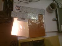
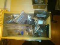
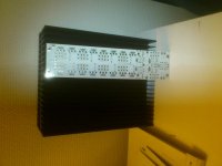
I think it is good idea to upload some pics to complement the gb.
This is my v3 version
This is my v3 version
Attachments
![DSC_0279[1].jpg](/community/data/attachments/295/295049-d38796ee245a3614405ef6a2f4fa709c.jpg)
![DSC_0280[1].jpg](/community/data/attachments/295/295056-97ec13cfd0fc30fb37d8f36e1ca0ea3e.jpg)
![DSC_0285[1].jpg](/community/data/attachments/295/295062-f310d1d129544f177f606195a0b4dc03.jpg)
- Status
- This old topic is closed. If you want to reopen this topic, contact a moderator using the "Report Post" button.
- Home
- Group Buys
- F5T Premium kit GB