I just enclosed the DAC in a small box. The wires are re-arranged as close to the enclosure as possible.
The transformer and the rectifier diodes (MSR860s) are put in another aluminum box.
In addition, I swapped the C8 with a Nichicon SMD tantalum 4.7uF capacitor. The sound became slightly cleaner to my ear.
Marlowe, why don't you put the diodes inside the same box with the DAC? so that from the PSU Box to the DAC Box the power transmission is in AC...
Is there advantage of carry it in DC over AC? I thought carry electricity in the longer cable would be beneficial in AC, since AC do not induce electro magnetic stray....?
Marlowe I missed your post. Neat build again but Ray has a very good point regarding the charge pulses. Either go for a one box solution or make a separate DC supply. AC does pick up RF more easy than DC IMHO. So DC is the way to go. As a sidenote: switching DC is not favorable for known reasons. And I would not put my money on SC transformers. You were telling that the EUVL DAC and ours sound alike with all these nice parts on the EUVL DAC ? That is a positive message. Will you be tweaking our DAC too ? Please let us know how things develop.
I am glad the 4.7 µF tantalium cap worked out well. I guess it should be changed in the BOM and in the schematic. So to all readers: change C8 to 4.7 µF tantalium as it will do better work than the original part. I have asked our COO to change this in the BOM/schematic if he can find an opportunity in these harsh economic times. We work in shifts now to help all our PCB buying customers. There is no limit in guaranteeing satisfaction to you all. You see our newly acquired marketing manager points me in the right direction.
And Syklab is called Syklab not Skylab but that can have been an error on his part")
I am glad the 4.7 µF tantalium cap worked out well. I guess it should be changed in the BOM and in the schematic. So to all readers: change C8 to 4.7 µF tantalium as it will do better work than the original part. I have asked our COO to change this in the BOM/schematic if he can find an opportunity in these harsh economic times. We work in shifts now to help all our PCB buying customers. There is no limit in guaranteeing satisfaction to you all. You see our newly acquired marketing manager points me in the right direction.
And Syklab is called Syklab not Skylab but that can have been an error on his part
Last edited:
Hi JP,
I start using Syklab as my call sign for over 15 years already, originally I wanted to use skylab for my domain name but that was taken so I changed it a bit to Syklab.
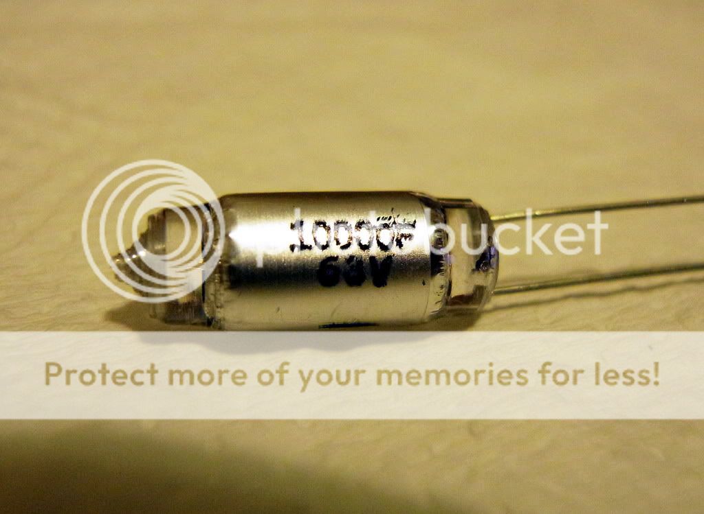
By the way, I pickup few of these POLYSTYRENE FILM CAPACITOR 10000pF 63V +/-1% to try it on the S/pdif input see if it is good idea or not.
Best regards.
I start using Syklab as my call sign for over 15 years already, originally I wanted to use skylab for my domain name but that was taken so I changed it a bit to Syklab.
By the way, I pickup few of these POLYSTYRENE FILM CAPACITOR 10000pF 63V +/-1% to try it on the S/pdif input see if it is good idea or not.
Best regards.
What's in a name ? I personally do not fully understand why "handles" have been invented or why I would have to pick an "internet name". In once had a good laugh when a friends 15 year old daughters computer had problems with email. I changed the settings and asked if she could send a test email to her father. I was watching the screen of her fathers laptop computer together with her father and there it was : an email from "sexatthebeach19XX@hotmail.com.....Two red faces.....
So I use my name with which I was born. The KISS approach maybe.
I would not be surprised if the styroflex cap performs worse than SMD parts in this application (inductivity, too large etc.) but let me know how it works out. A PPS SMD would be nice to try (when I think of it).
Like this one:
http://il.farnell.com/panasonic/echu1c103jx5/capacitor-0805-10nf-16v/dp/9695028
Last edited:
Yeah I know everybody does (except for a few) but sometimes I ask myself where the fun is in "satan666", "iron eagle", "black knight", "Testarossa4life" etc.
Then you see the guys in real life and they turn out to be wimpy scooter driving pale faced gaming nerds
Then you see the guys in real life and they turn out to be wimpy scooter driving pale faced gaming nerds
Last edited:
I am glad the 4.7 µF tantalium cap worked out well. I guess it should be changed in the BOM and in the schematic. So to all readers: change C8 to 4.7 µF tantalium as it will do better work than the original part.
Hi Jean Paul
Will a 16v do the trick ?
BTW it's a polarised part even if it's a 1210 SMD device.
Could you point it's right connexion in the Build Guide ?
Regards
Phil
Hi Phil, of course it is polarized and you have a good point as tantalium caps severely dislike being reverse connected. Exactly: boom ! I already informed Subbu if the documents can be changed. The + of the cap should be connected to bead L3. Please carefully check all tantalium caps while placing them as most of them have their + marked opposed to the more standard - marking on standard electrolytic caps.....
A 4.7 µF 10 V or 16 V tantalium cap is the one you would like to use. For instance the same one as the other 4.7 µF tantalium caps already used on the DAC board. Why oh why is this spelling checker complaining every time I write tantalium or aluminium changing them to tantalum and aluminum ?
A 4.7 µF 10 V or 16 V tantalium cap is the one you would like to use. For instance the same one as the other 4.7 µF tantalium caps already used on the DAC board. Why oh why is this spelling checker complaining every time I write tantalium or aluminium changing them to tantalum and aluminum ?
Last edited:
Why oh why is this spelling checker complaining every time I write tantalium or aluminium changing them to tantalum and aluminum ?
Because that's the correct spelling.
Regards
Not in the periodical system which I consider to be leading ?! Aha just checked : both aluminium and aluminum are mentioned being one and the same but "tantalium" is apparently only used in Europe. Strange thing is that most end with "ium" so with "i". Niobium, iridium etc. Mysterious.
Let's say that both tantalium and tantalum 4.7 µF SMD caps can be used for C8. Both will do better work at that spot. You can build the DAC in an aluminium case but an aluminum case will do just as well with a slight preference for aluminium as it has slightly better properties
Let's say that both tantalium and tantalum 4.7 µF SMD caps can be used for C8. Both will do better work at that spot. You can build the DAC in an aluminium case but an aluminum case will do just as well with a slight preference for aluminium as it has slightly better properties
Last edited:
A 4.7 µF 10 V or 16 V tantalium cap is the one you would like to use.
For instance the same one as the other 4.7 µF tantalium caps already used on the DAC board.
Thank you Jean Paul for confirmation : C8+ connected to bead L3.
However, I can't find were you've noticed another 4.7uF tantalium...
As recommended earlier after having one DAC with an oscillating reg: all 4 x 4.7 µF caps after the regs should be tantalium/tantalum caps as the regs dislike 4.7 µF ceramic caps because of too low ESR ...
Data sheet of MIC5205 is clear about this too. I actually used tantalium/tantalum caps there in nearly all my assembled DACs but tried ceramic 4.7 µF caps once on a rev. 2 board and it was not OK. As another solution I suggested to swap the 1 µF at the input and the 4.7 µF at the output to the other way around so 1 µF at the output and the ceramic 4.7 µF at the inputs but it would be best to use tants at the outputs.
Yes progress has some sharp edges. I wish we can change BOM/schematic/build guide so things will be clear again.
Last edited:
So the parts concerned by Tantalum replacement are :
1° - C19, C22, C26, C29 and C8 for SE
2° - C19, C22, C26 and C8 for BAL
Would this one be a good candidate : http://fr.mouser.com/ProductDetail/...=sGAEpiMZZMuEN2agSAc2pj8MbHwJGci9U2mVu6qTaAc=
Please Jean Paul confirm...
Phil
PS : Yes, changes in BOM, schematic and build guide are welcome as those parts are polarized.
Last edited:
Hi VT67, yes it could fit too
The Vishay ref shows a 5 Ohms ESR at Mouser's, and 3.5 Ohms on the datasheet.
This value is mentionned in the MIC5205 datasheet :
"...The output capacitor should have an ESR (effective series resistance) of about 5Ω or less and a resonant frequency above 1MHz..."
Thank you for your input !
Phil
The Vishay ref shows a 5 Ohms ESR at Mouser's, and 3.5 Ohms on the datasheet.
This value is mentionned in the MIC5205 datasheet :
"...The output capacitor should have an ESR (effective series resistance) of about 5Ω or less and a resonant frequency above 1MHz..."
Thank you for your input !
Phil
Last edited:
- Status
- This old topic is closed. If you want to reopen this topic, contact a moderator using the "Report Post" button.
- Home
- Group Buys
- ES9023 / WM8804 S/PDIF DAC Group Buy