
MrSavage,
do you really need 4 Soft-Power-On - PCBs?
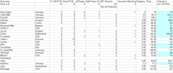
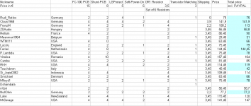
You can connect 3 transformers ( 2 transformers 2 x 25 VAC for the backends, 1 transformer for the frontend) to one Soft-Power-On PCB!
And: don't you need the FUTABA MPC75 0R1 emitter resistors?
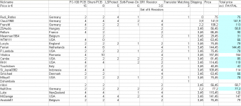
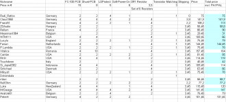
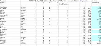
Find enclosed the modified order.
You can use PAYPAL to transfer the total sum incl. PAYPAL tax to: RRozek@t-online.de
The prices are in € (EURO).
Best regards - Rudi_Ratlos
P.S. I hope that your letter does not exceed the weight of 500gr.
do you really need 4 Soft-Power-On - PCBs?
You can connect 3 transformers ( 2 transformers 2 x 25 VAC for the backends, 1 transformer for the frontend) to one Soft-Power-On PCB!
And: don't you need the FUTABA MPC75 0R1 emitter resistors?
Find enclosed the modified order.
You can use PAYPAL to transfer the total sum incl. PAYPAL tax to: RRozek@t-online.de
The prices are in € (EURO).
Best regards - Rudi_Ratlos
P.S. I hope that your letter does not exceed the weight of 500gr.
Attachments
Last edited:
MrSavage,
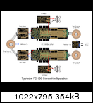
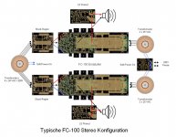
this is the way the FC-100 is meant to be set up in a typical stereo - configuration:
http://www.abload.de/img/stereo-configt5bx6.png
The 220/125VAC mains connect to the "Soft-Power-On - PCB".
This PCB has a small transformer on board, and it is this little transformer that you switch on.
The Soft-Power-On - PCB delimits the mains' current to about 4A during the time, the inrush-current flows
(0.7 secs, determined by the timer's external components).
The 3 transformers used to operate the FC-100 in this typical setup (2 transformers with 2 x 25 VAC each for the backends,
1 transformer 4 x 34 VAC to for the frontends) connect to the PCB-connector of this PCB.
The FC-100 PCBs have the backend-PSU on-board; the two 2x25VAC transformers connect to the onboard-PSUs.
The secondaries of the 4 x 34VAC transformer connect to 2 shunt-regulators, providing a very stable +/-39VDC voltage at 21.5mA
to the frontends of the AMP's PCBs.
The speakers' outputs connect to the "Speaker-Protection-PCBs" that protect your speakers from a malfunction of the AMP.
So: in a typical setup of the FC-100 you need:
- 2 transformers, 2 x 25 VAC
- 1 transformer, 4 x 34 VAC
- 1 Soft-Power-On PCB
- 2 FC-100 PCBs
- 2 Shunt-regulator PCBs
- 2 Speaker Protection PCBs
Best regards - Rudi_Ratlos
this is the way the FC-100 is meant to be set up in a typical stereo - configuration:

http://www.abload.de/img/stereo-configt5bx6.png
The 220/125VAC mains connect to the "Soft-Power-On - PCB".
This PCB has a small transformer on board, and it is this little transformer that you switch on.
The Soft-Power-On - PCB delimits the mains' current to about 4A during the time, the inrush-current flows
(0.7 secs, determined by the timer's external components).
The 3 transformers used to operate the FC-100 in this typical setup (2 transformers with 2 x 25 VAC each for the backends,
1 transformer 4 x 34 VAC to for the frontends) connect to the PCB-connector of this PCB.
The FC-100 PCBs have the backend-PSU on-board; the two 2x25VAC transformers connect to the onboard-PSUs.
The secondaries of the 4 x 34VAC transformer connect to 2 shunt-regulators, providing a very stable +/-39VDC voltage at 21.5mA
to the frontends of the AMP's PCBs.
The speakers' outputs connect to the "Speaker-Protection-PCBs" that protect your speakers from a malfunction of the AMP.
So: in a typical setup of the FC-100 you need:
- 2 transformers, 2 x 25 VAC
- 1 transformer, 4 x 34 VAC
- 1 Soft-Power-On PCB
- 2 FC-100 PCBs
- 2 Shunt-regulator PCBs
- 2 Speaker Protection PCBs
Best regards - Rudi_Ratlos
Attachments
Last edited:
Hi Rudi,
I have decided to also take 2 - LS Protect PCB's and 2 - Soft-power on PCB's. So, I owe you 78 euros total Correct? Will send you the funds today.
I have two of these transformers:http://www.diyaudio.com/forums/group-buys/133796-gb-rmi-fc100-parts-11.html
Post # 107.
So, I need another 2 x 34V transformer correct?
Last edited:
Shunt Regulator transformer
How much wiggle room is there on the VAC output of the shunt regulator power supply transformer?
Is 35VAC too high? Is 33VAC too low? Is it just a matter of dissipating more heat in the regulator itself (if VAC is too high)? I ask because 35VAC output transformers are more easily found, at least in the US, than 34 VAC transformers.
Thanks,
Ryan
@Cambe, the total price is 85€.
@Ryan: I am currently operating the frontend-shunt from a 35VAC transformer. ZSAUDIO uses a 30VAC transformer, if I remember this correctly.
Mihai designed the shunt with an output of +/-39VDC rated at 21.5mA (!) to the frontend.
Please keep in mind that a standard 36V zener-diode has a deviation of 10%, that mains fluctuate, that the transformer's output changes according to the load, ...
In my eyes any transformer giving between 32 - 35 VAC will do it.
Best regards - Rudi_Ratlos
Attachments
Hi Rudi!
Is the soft start board the same as for your TO-3 amp group buy? I now want to buy just one board so that I can build the TO-3 in monobloc form!
I this is the same please include me for just the one soft start board. OR if you have a spare from the TO-3 group buy I would like it.
Many thank again,
Brian.
Gentlemen,
I have just finished the BoMs of the PCBs of my FC-100 group-buy offer.
Have a look at post #84 where I have shown a typical configuration of the FC-100 amplifier.
I have included the BoMs of the different PCBs in form of URLs.
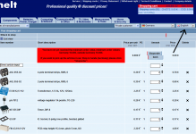
When you open an URL, please change the language to "English" (as shown on the attached image).
This is the BoM of the FC-100 amplifier-PCB:
https://secure.reichelt.de/index.html?;ACTION=20;AWKID=565875;PROVID=2084
The BoM does not include the emitter-resistors, the MKP1839 / 1µF capacitor and the NJL transistors.
This is the BoM of the integrated PSU:
https://secure.reichelt.de/index.html?;ACTION=20;AWKID=565881;PROVID=2084
The two 10.000µF capacitors per rail are set up in a C-R-C configuration.
The resistor (0R1/5W) is not included in the BoM.
You can use a C-L-C configuration (using a 1mH choke) as well or a combination of both: C-L/R-C.
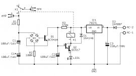
This is the BoM of the shunt regulator:
https://secure.reichelt.de/index.html?;ACTION=20;AWKID=563980;PROVID=2084
I included 2.200µF capacitors / 50V, but take care, if you use 34VAC or 35VAC transformers.
You will be on the safe side using 2.200µF/63V capacitors.
This is the BoM of the Speaker Protection PCB:
https://secure.reichelt.de/index.html?;ACTION=20;AWKID=564957;PROVID=2084
Take care that you will use a relay with the required grid.
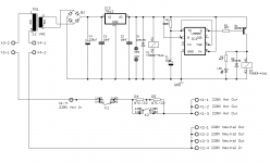
This is the BoM of the Soft-Power-On PCB:
https://secure.reichelt.de/index.html?;ACTION=20;AWKID=565919;PROVID=2084
The BoM does not include the NTCs (I used 2 x 22R / @25 degree NTCs).
You can also use 1 (or 2) big power resistors and mount them vertically.
Regarding the used transformers:
You need 1 (or 2) 2 x 25 VAC transformers for the Backend-PSU with high wattage and 1 (or 2 ) 32 - 35VAC transformers
for the frontend (shunt regulator) with very small wattage (30W).
I will course include the BoMs in my "FC-100 Builder's Manual" which I plan to complete by the end of this week.
Best regards - Rudi_Ratlos
I have just finished the BoMs of the PCBs of my FC-100 group-buy offer.
Have a look at post #84 where I have shown a typical configuration of the FC-100 amplifier.
I have included the BoMs of the different PCBs in form of URLs.
When you open an URL, please change the language to "English" (as shown on the attached image).
This is the BoM of the FC-100 amplifier-PCB:
https://secure.reichelt.de/index.html?;ACTION=20;AWKID=565875;PROVID=2084
The BoM does not include the emitter-resistors, the MKP1839 / 1µF capacitor and the NJL transistors.
This is the BoM of the integrated PSU:
https://secure.reichelt.de/index.html?;ACTION=20;AWKID=565881;PROVID=2084
The two 10.000µF capacitors per rail are set up in a C-R-C configuration.
The resistor (0R1/5W) is not included in the BoM.
You can use a C-L-C configuration (using a 1mH choke) as well or a combination of both: C-L/R-C.
This is the BoM of the shunt regulator:
https://secure.reichelt.de/index.html?;ACTION=20;AWKID=563980;PROVID=2084
I included 2.200µF capacitors / 50V, but take care, if you use 34VAC or 35VAC transformers.
You will be on the safe side using 2.200µF/63V capacitors.
This is the BoM of the Speaker Protection PCB:
https://secure.reichelt.de/index.html?;ACTION=20;AWKID=564957;PROVID=2084
Take care that you will use a relay with the required grid.
This is the BoM of the Soft-Power-On PCB:
https://secure.reichelt.de/index.html?;ACTION=20;AWKID=565919;PROVID=2084
The BoM does not include the NTCs (I used 2 x 22R / @25 degree NTCs).
You can also use 1 (or 2) big power resistors and mount them vertically.
Regarding the used transformers:
You need 1 (or 2) 2 x 25 VAC transformers for the Backend-PSU with high wattage and 1 (or 2 ) 32 - 35VAC transformers
for the frontend (shunt regulator) with very small wattage (30W).
I will course include the BoMs in my "FC-100 Builder's Manual" which I plan to complete by the end of this week.
Best regards - Rudi_Ratlos
Attachments
- Status
- This old topic is closed. If you want to reopen this topic, contact a moderator using the "Report Post" button.
- Home
- Group Buys
- Roender's FC-100 Rev.1 Group-Buy