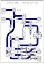
Marjohn, I have a sufficiently big quantity of 2SK170BL at hand, all of which have an IDss of > 9mA!
My little test-rig (see attached image) confirms this.
If you like to have the EAGLE-files of this small test-rig, I will send them to you - no problem: "We are DIY."
I will also be able to offer you well matched pairs of 2SK170BL (...must have the same Vgs +/- 1mV at Id=6.25mA),
once I know how to adjust my LTSpice model.
Best regards - Rudi_Ratlos
Attachments
Roender.
I have a problem.
I have added a separate regulated supply to the FC100.
The FC100 PCB in this GB uses a single bridge rectifier. That limits the Main Audio Ground to be connected to the Centre tap of a dual secondary transformer. That ground line runs right along the middle of the PCB and does the same on your original PCB.
I am working with the original PCBs at the moment.
I have a choice of where to connect the auxiliary PSU Zero Volts to the main PSU.
a.) At the Zero Volts on the wires from the centre tap
b.) at the Power input connector on the PCB.
c.) at the hole for the ON board Ground at the left end (next to spk out)
d.) at the hole for the ON board Ground at the right end (next to the NFB tapping solder point).
The "problem":-
If I connect the regulated output with a twisted triplet to the three points at the right hand end, I get an ~4V offset in the regulated output voltages. i.e. the regulated +-50Vdc becomes +46Vdc and -54Vdc. Even the 4 smoothing caps on the reg PCB have offset voltages. They change from +-58Vdc, to +54Vdc and -62Vdc.
If I connect instead the INPUT ground of the regulator to any of the first three listed above the offset becomes zero as near as I can measure. I see a very few millivolts of difference depending at what ends of the long Ground line I measure at.
I cannot see why connecting the OUTPUT from the reg to the right most ground creates this offset. I have puzzled for a few days repeating the experiment with different regulators and different transformers and different wiring and I cannot eliminate the offset.
It makes the cascode in the LTP sink run hotter. I will probably increase the size of the sink from 30C/W as I have done with the first of the Rudi PCBs.
I will hand draw what I have described and post a pic later today, or at the latest tomorrow.
Last edited:
And that is why I respect the Euvl team in the way they matched the output mosFETs of the F5x.I second that. It's not an easy job and took many hours to closely match jfets.
They developed a machine curve tracer that automatically logged the results and then used some software to select the matches from those many thousands of results.
A similar system could be used to these jFETs, but having read their testing procedure I think the resources they brought to the table would probably exceed the cost of all the F5Xs that are being built (about 50 so far).
Jean, I had to rebuild the carts!
Here they are again:
FC-100_Speaker Protection (needed 2 times):
https://secure.reichelt.de/index.html?;A…107;PROVID=2084
FC-100_Soft-Power-On (needed 1 time):
https://secure.reichelt.de/index.html?;A…309;PROVID=2084
FC-100_Shunt-Regulator (needed 2 times):
https://secure.reichelt.de/index.html?;A…804;PROVID=2084
FC-100_Amplifier (needed 2 times):
https://secure.reichelt.de/index.html?;A…339;PROVID=2084
FC-100_Backend-PSU (needed 2 times):
https://secure.reichelt.de/index.html?;A…041;PROVID=2084
Best regards - Rudi_Ratlos
Marjohn, I have a sufficiently big quantity of 2SK170BL at hand, all of which have an IDss of > 9mA!
My little test-rig (see attached image) confirms this.
If you like to have the EAGLE-files of this small test-rig, I will send them to you - no problem: "We are DIY."
I will also be able to offer you well matched pairs of 2SK170BL (...must have the same Vgs +/- 1mV at Id=6.25mA),
once I know how to adjust my LTSpice model.
Best regards - Rudi_Ratlos
Thanks for sharing the test rig Sir, yeah sure sir just pm me when you have already matched pairs of this transistors.
regards,
marjohn
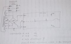
The grounding scheme with regulator for the front end Vcc/Vdd
There is no chassis and as a result no complications with extra connections to PE.
Hi Andrew,
You should connect A with E. Your topology is not suitable for ground separation between front end and power stage because there is only one common AC central tape.
Kind regards,
Mihai
Last edited:
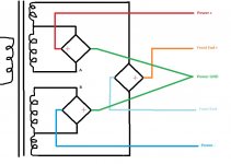
How do the Roender PCBs connect together with dual bridges instead of single bridges?
This will not apply to the Rudi PCBs because the amp PCB has on board single bridge.
But I will probably use a common transformer arrangement for all the Roender and Rudi PCBs.
Do you mean dual bridge per channel? I had never use that configuration.
Something like that? I don't think it's a good solution.
Where are you going to tap for frontend ground? If A and B points are going to be connected together in order to get the frontend ground then there is no point for dual bridge power stage.
IMHO, use a separate transformer for front end PSU
Where are you going to tap for frontend ground? If A and B points are going to be connected together in order to get the frontend ground then there is no point for dual bridge power stage.
IMHO, use a separate transformer for front end PSU
Attachments
Last edited:
Roender.
That arrangement does not work.
The dual secondaries demand that the extra taps must also be dual secondaries and separate. The single bridge is not compatible with the dual bridge when joined at the AC side.
I have a separate transformer for the extra 9+9Vac. That is why it is shown without the common core "|||" in the diagram.
What I don't have is a Low VA, 35+35Vac to 40+40Vac transformer.
I do have a doubler that gets the 9Vac upto 80Vdc open circuit, that falls to ~60 to 70Vdc depending on the loading. Typical droop for a doubler style circuit. Dual 9Vac secondaries + quad doublers, gets me +-80Vdc separately. I can join then at the DC side and bypass the single bridge in the reg PCB.
I'm going to post those experiments in a new Thread shortly.
Last edited:
indeed, rough batching reduces labour a lot.
Are you the Franz that posted an LTP test jig & procedure?
The equal Gate Voltage and equal Source Voltage style of LTP matching is VERY sensitive to small differences in gm. That gm difference results in difference in output current. That output current is read off across the two Drain resistors.
Three DMMs would be ideal. One across each Drain resistor and one across the Drains.
My best matches got to <0.2% of Drain current difference over a range of Id from 100% of Idss down to 20% of Idss. But the yield of these extreme matches is very low. I did get a high yield of <1% diff @ >=25%Idss. These are what I was selling to UK buyers. But most ended up getting sold to foreigners for DCB1. What a waste I kept telling my enquiring customers, but they bought anyway. Some folk have too much money.
There is a perception that dearer components play music better.
Last edited:
No, as far as I can remember. Can you direct me to that post, please?
Testing each JFET separately could increase the speed of the matching process. I intend to use a HP 34907A data aquisition unit and a proper test setup for measuring and recording the data.
Testing each JFET separately could increase the speed of the matching process. I intend to use a HP 34907A data aquisition unit and a proper test setup for measuring and recording the data.
Last edited:
Manuel, it has been my error! I copied the URL in a wrong way.
Here they are again:
FC-100_Speaker Protection (needed twice):
https://secure.reichelt.de/index.html?;ACTION=20;AWKID=650107;PROVID=2084
FC-100_Soft-Power-On (needed once):
https://secure.reichelt.de/index.html?;ACTION=20;AWKID=650309;PROVID=2084
FC-100_Shunt-Regulator (needed twice):
https://secure.reichelt.de/index.html?;ACTION=20;AWKID=650804;PROVID=2084
FC-100_Amplifier (needed twice):
https://secure.reichelt.de/index.html?;ACTION=20;AWKID=652339;PROVID=2084
FC-100_Backend-PSU (needed twice):
https://secure.reichelt.de/index.html?;ACTION=20;AWKID=650041;PROVID=2084
Not included in the carts, because Reichelt does not have the parts on stock, are:
NJL-transistors, MJE15034/MJE15035, Toshiba 2SA/2SC transistors, MKP1839 / 1µF, MPC74 0R1 emitter resistors and DC blocking cap.
Best regards - Rudi_Ratlos
- Status
- This old topic is closed. If you want to reopen this topic, contact a moderator using the "Report Post" button.
- Home
- Group Buys
- Roender's FC-100 Rev.1 Group-Buy