No worries, O/I the way you did it looks fine (the I is just a single stroke).
Have a quick measurement from the center of the volume control hole to the line below it. The standard knob that RS included in the BOM has an 8mm radius. Make sure the knob doesn't cross the line.
I think leaving the engraving natural is fine. There is plenty of contrast.
Have a quick measurement from the center of the volume control hole to the line below it. The standard knob that RS included in the BOM has an 8mm radius. Make sure the knob doesn't cross the line.
I think leaving the engraving natural is fine. There is plenty of contrast.
@flynhawaiian
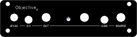
- O/I or 0/1 doesn't matter, with this font it looks the same, i tried this in FPD.
- your design looks good, i also draw it before i saw yours, some little differences
* a little more space between text and lines
* "2" as lowersubscript like NwAvGuy
* Objective2 a little lower, a little more distance to the edge
* text and line a little bit more distance to holes
* i centered all text with the holes above them
i dont know how to upload my fdp-file, if you like i can perhaps send it to you by email; you could send me a PM.
- i think unfilled is oke, i used the thinnest linewidth of 0,2mm
Attachments
Last edited:
No worries, O/I the way you did it looks fine (the I is just a single stroke).
Have a quick measurement from the center of the volume control hole to the line below it. The standard knob that RS included in the BOM has an 8mm radius. Make sure the knob doesn't cross the line.
I think leaving the engraving natural is fine. There is plenty of contrast.
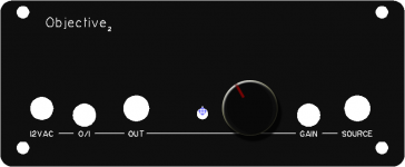
the volumeknob will cross the line, i think that is acceptable,
lowering the line/text will not work, it's too much
natural fill seems fine to me also
I need to get back to work, so I will not be checking the forums for a few hours. If I don't I'm going to be REALLY REALLY far behind!
Arch I sent you a pm, I didn't make the other changes other than just moving it from a superscript to a subscript. Because I didn't have the time, but lets work on it later or tonight if your on. I’m in the PST time zone, so I believe we are 9 hours off. Ie here its 1:30pm there its 10:30pm.
Everything is centered with the holes and everything is vertically lined up! I would really like to find a supplier for some aluminum knobs to go along with this panel. If I can figure out how to make FPE give me dimensions on everything, including holes etc. I can send this whole thing to a manufacturer in china and see about making the panels, knobs and the boxes.
")
does 0/1 make sense or POWER?
no label for volume?
-joe
1. - 0/1 makes sense
- this symbol is used on many devices
- it is the only way to turn the amp on even a child will find out
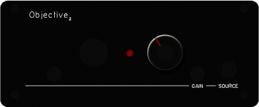
2. - no label for volume makes sense
- one rotary knob on an amp and most of us will find out it is the volumeknob
- because of the diameter of the rotaryknob the text will not be very visible, lowering the textline brings trouble elsewhere, lowering the text volume does not look professional
does 0/1 make sense or POWER?
no label for volume?
-joe
1.
- this symbol is used on many devices
- it is the only way to turn the amp on even a child will find out
- 0/1 makes sense
2.
- because of the diameter of the rotaryknob the text will not be very visible, lowering the textline brings trouble elsewhere, lowering the text volume does not look professional
- one rotary knob on an amp and most of us will find out it is the volumeknob
- no label for volume makes sense
Any chance I can get in on this GB? If so, put me down for 2 panels to the US.
Thanks,
Marvin
Sure, no problem.. Flynhawaiian is getting pricing on the last design that Architect did, and we'll have to figure out shipping costs etc.. and then do a formal Group Buy
OK.. so I've been playing around with Architect's design, to adapt it to the B3 (mini Desktop) case. The original suggestion by RocketScientist was to flip the board around so that most of the connectors are at the back, along with a pair of new RCA jacks, and just bring a volume control, 1/4" jack and possibly a LED to the front. Unfortunately that also means that the Power and Gain switches are also at the back.
This alternative idea would be to move the Power connector to the back, and add the 1/4" jack to the front (it has to be on the left to avoid the batteries, for those that want to maintain battery powered capability). Since there would only be 3 holes required in the back panel, most people with access to a drill(or a friend who has one) could take care of the holes themselves, rather than requiring the precision of a machined panel.
The single unit price is $22ish.. qty 20 brings it down to $15.50. I'll be buying 20 myself, since I need 18 and it will be cheaper to hit the 20 price break than buying 18. It wouldn't take many people who want to build a "desktop" to get to 30 or more. The B2(the standard panel) qty 1 price is just under $22, and it's qty 30 price was under $11, so this one will probably be about the same.. (all these prices do not include shipping etc, and are for ballpark pricing)
Here are some ideas:
(opinions or suggestions are welcomed. Remember that the batteries occupy a rectangle of 53mm wide x 17.5mm high on the right side of the amp, at about the level of the label line, to approximately half way between the LED hole and the 3.5 mm output jack)
Attachments


Last edited:
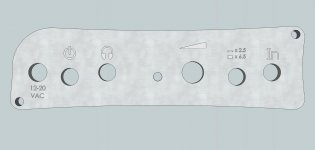
hi mrslim,
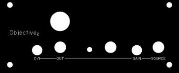
i see you moved [12VAC] to the backside
and i see you added a large hole, what is it for?
is it true this panel is 25mm higer and also the small screwholes at the top are moved up 25mm?
i made a frontdesign doing nothing, but change the frontsize.
i think we should first decide what's on front.
i see you moved [12VAC] to the backside
and i see you added a large hole, what is it for?
is it true this panel is 25mm higer and also the small screwholes at the top are moved up 25mm?
i made a frontdesign doing nothing, but change the frontsize.
i think we should first decide what's on front.
Attachments
Last edited:
- oke i see you added a standard size jackoutput
- perhaps two rca-input on the backside would also be a good thing
- i myself had the idea to make a convertercable with standar jack input and minijack output
- perhaps it would look nice with the led in the middle and jack and volume to beside it; can we mount the volumepot to the front?
- we can skip text 0/1 because its function is very obvious in the layout
Attachments
hi mrslim,
is it true this panel is 25mm higer and also the small screwholes at the top are moved up 25mm?
i made a frontdesign doing nothing, but change the frontsize.
i think we should first decide what's on front.
Yes the difference in height between the panels is 25mm (29.5 vs 44.5) and the distance between the screws also increases by 25mm (21.5 to 36.5)
- oke i see you added a standard size jackoutput
- perhaps two rca-input on the backside would also be a good thing
- i myself had the idea to make a convertercable with standar jack input and minijack output
- perhaps it would look nice with the led in the middle and jack and volume to beside it; can we mount the volumepot to the front?
- we can skip text 0/1 because its function is very obvious in the layout
This one is similar to RocketScientist's original suggestion, except for the addition of the 1/4" jack. RS's whole point of suggesting the B3 case was to make room for the RCA's and the 1/4" jack to make it more "hospitable" to desktop connections. Leaving off the 1/4" jack makes using the taller case rather irrelevant, since if you are just going to use a 1/4 to 3.5 mm adapter, then you can use RCA to 3.5 mm adapters too, and just use the B2 case.
It's not obvious in your image if there is a 3.5mm or 1/4" jack on the front panel, and what's the point of having a Source connection at the front(or should that say "Headphone")? Also, you need to make sure everything (including the LED) is at least 53 mm to the right to leave the space for the batteries, and there is clearance for the other components on the board (have to check that on mine also).
I'm torn since moving the Vol pot and the 1/4" jack to the new "front" is cleaner looking, it is also less practical because the gain and power switches are still at the back.
It also requires users to buy two panels vs one.
Last edited:
OK.. so I've been playing around with Architect's design, to adapt it to the B3 (mini Desktop) case. The original suggestion by RocketScientist was to flip the board around so that most of the connectors are at the back, along with a pair of new RCA jacks, and just bring a volume control, 1/4" jack and possibly a LED to the front. Unfortunately that also means that the Power and Gain switches are also at the back.
This alternative idea would be to move the Power connector to the back, and add the 1/4" jack to the front (it has to be on the left to avoid the batteries, for those that want to maintain battery powered capability). Since there would only be 3 holes required in the back panel, most people with access to a drill(or a friend who has one) could take care of the holes themselves, rather than requiring the precision of a machined panel.
The single unit price is $22ish.. qty 20 brings it down to $15.50. I'll be buying 20 myself, since I need 18 and it will be cheaper to hit the 20 price break than buying 18. It wouldn't take many people who want to build a "desktop" to get to 30 or more. The B2(the standard panel) qty 1 price is just under $22, and it's qty 30 price was under $11, so this one will probably be about the same.. (all these prices do not include shipping etc, and are for ballpark pricing)
Here are some ideas:
(opinions or suggestions are welcomed. Remember that the batteries occupy a rectangle of 53mm wide x 17.5mm high on the right side of the amp, at about the level of the label line, to approximately half way between the LED hole and the 3.5 mm output jack)
For a desktop version I think the following layout/configuration makes sense simply from a usability point of view:
Front panel:
Volume
Power on/off
Output(s)
LED
Back panel:
Input(s)
Gain switch
Power in ("12VAC")
The gain switch could go on the front too, but I think it would be used infrequently in this application.
- Status
- This old topic is closed. If you want to reopen this topic, contact a moderator using the "Report Post" button.
- Home
- Group Buys
- O2 Front Panel GB Interest