Make sure the feedback cap is not rolling off the bass early.
It should have virtually no AC voltage across it when the amplifier is delivering maximum bass power.
The 22pF is nothing to do with bass. It is a stability compensation component.
Start with none and increase it gradually to a max of ~22pF.
Sometimes this cap can make stability worse, particularly if it is slightly too big.
It also allows RF picked up by the speaker cables to directly enter the -IN of the amplifier. That is really bad !!!!
Last edited:
Junie, I had the chance to buy a couple of MPSA18 some time ago and use them as differential pair. You can also use 2N5551 or BC550C.
Please take care and flip the MPSA18 or 2N5551 by 180 degrees due to different pinout from the 2SK170.
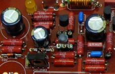
It would be best for you to insert the transistors into sockets (as show on the image below).
So you have the choice to take the pair of transistors that you like most.
Best regards - Rudi_Ratlos
Please take care and flip the MPSA18 or 2N5551 by 180 degrees due to different pinout from the 2SK170.
It would be best for you to insert the transistors into sockets (as show on the image below).
So you have the choice to take the pair of transistors that you like most.
Best regards - Rudi_Ratlos
Attachments
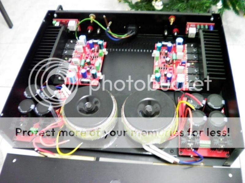
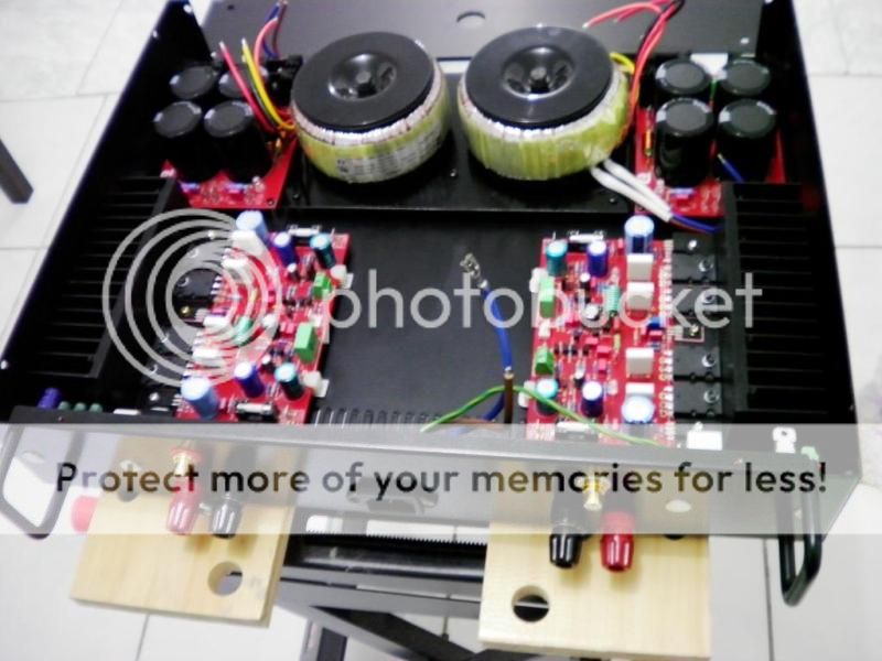
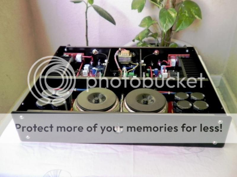
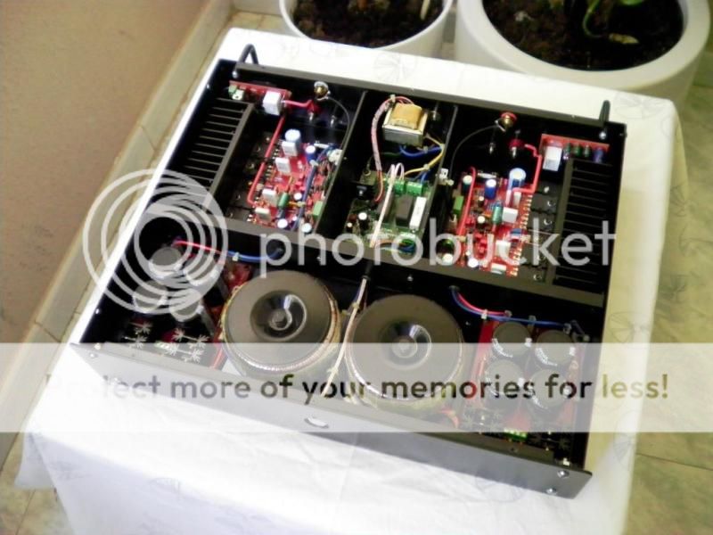
Junie, at first view your build looks very promising!
May I give you some hints?
1) Never do the 1st power-on without having a light-bulb tester installed!
2) Check the functionality of the PSUs first
3) Verify that none of the pins of any MJL output transistors, drivers and BD139 is in contact to the heatsink
4) Make sure that the potentiometers are preset to their max. values (i.e. 500R)
4) Remove the fuses and install a 10 Ohm / 0.25VA across the fuse-holders instead. This will prevent any "severe error" from damaging your output transistors, ...
I will keep my fingers crossed.
Best regards - enjoy the sound - Rudi
P.S. This is my SYMASYM:
http://www.abload.de/img/sim007fae98.jpg
May I give you some hints?
1) Never do the 1st power-on without having a light-bulb tester installed!
2) Check the functionality of the PSUs first
3) Verify that none of the pins of any MJL output transistors, drivers and BD139 is in contact to the heatsink
4) Make sure that the potentiometers are preset to their max. values (i.e. 500R)
4) Remove the fuses and install a 10 Ohm / 0.25VA across the fuse-holders instead. This will prevent any "severe error" from damaging your output transistors, ...
I will keep my fingers crossed.
Best regards - enjoy the sound - Rudi
P.S. This is my SYMASYM:

http://www.abload.de/img/sim007fae98.jpg
Last edited:
Rudi, a quick question on setting the right bias on the 2 stage SymaSYm. In the builder guide, you say each TO264 needs 50-55mA which translate to about 12 mV per 0.22R resistor. On the single output SymaSym shown in the guide, you adjust for 2 x 0.22R resistor to 24mV. So, what should the adjustment be for a 2 stage SymaSym across MP1-MP2 test point or should we use the 10 or 100R fuse bridge to measure the bias current a la "DX" ( 4X50 ma x 100R = 20V )? Thanks
Jean, MP1 and MP2 (points of measurement) connect to the emitters of transistor Q13( NPN) and Q16 (PNP) respectively. Two emitter resistors, R82 and R83, each 0R22, lie between them.
Adjust the potentiometer to 500 Ohm (max. value) first, then turn it to a lower value until about 24mV drops across these 2 emitter resistors.
The value of 24mV is a conservative value; if you have big heatsinks and use TO264- or even TO3- transistors, you can slightly raise this value!.
The 10 Ohm fuse-bypass resistor (in Germany called "fear-resistor") is a safeguard against shorts on your PCB, wrong components chosen, ....
Take a small wattage resistor (0.25W) that will melt, before any damage is done to your PCB.
Best regards - Rudi
Sorry Rudi, I did not make myself clear. When I assemble the amp as per the guide and do the bias adjustment with only 1 MJE4281 and 4302, I set it to 24m between MP!/MP2 no problem. But when I insert the second pair of MJE's, the value measured jumps to about 48mV - do I need to readjust the pot back to read 24 mV or leave it at aROUND 48 mV.
The other question was if it easier to adjust the bias measuring the voltage across say a 100R resistor instead of the fuses (after everything with the board as checked out okay) as was done with the DX type amps from Carlos? Is that not easier to do???
Thanks again, Jean
The other question was if it easier to adjust the bias measuring the voltage across say a 100R resistor instead of the fuses (after everything with the board as checked out okay) as was done with the DX type amps from Carlos? Is that not easier to do???
Thanks again, Jean
Jean, I misunderstood your question.
My SYMASYM-PCB works with either a single pair or with 2 pairs of NPN/PNP output transistors.
In my builder's guide I told you to:
- only solder a single pair of NPN/PNP
- use light-bulb tester
- do not insert a fuse but use a 10 Ohm / 0.25W resistors, soldered across the fuse-holder
- preset the potentiometer to its max. value
Then switch power on. Are you able to adjust the SYMASYM as written?
If so:
- solder the 2nd pair of NPN/PNP, if you have, if you like / want to use, ...
- make sure once more that none of any transistor's legs contacts to the heatsink
- remove the 10 Ohm resistor and insert a fuse
- remove the light-bulb tester
- preset once the potentiometer to its max. value
Then switch power on again and adjust the SYMASYM once more.
This is how I meant it.
Best regards - Rudi_Ratlos
MJEs, not for output devices..................... When I assemble the amp as per the guide and do the bias adjustment with only 1 MJE4281 and 4302, I set it to 24m between MP!/MP2 no problem. But when I insert the second pair of MJE's, the value measured jumps to about 48mV - do I need to readjust the pot back to read 24 mV or leave it at aROUND 48 mV.
The other question was if it easier to adjust the bias measuring the voltage across say a 100R resistor instead of the fuses (after everything with the board as checked out okay) as was done with the DX type amps................
If you havean output bias that changes from 24mVre to 48mVre by adding and extra pair of output then you have a broken amplifier.
Revert to single output pair and check what you post and edit the data if necessary.
DO NOT set and measure the amplifier quiescent current by measuring across 100r resistors in the fuse location. This is very bad practice. DX has been told this repeatedly but he refuses to listen and keeps posting the same wrong information.
Last edited:
")
 !!
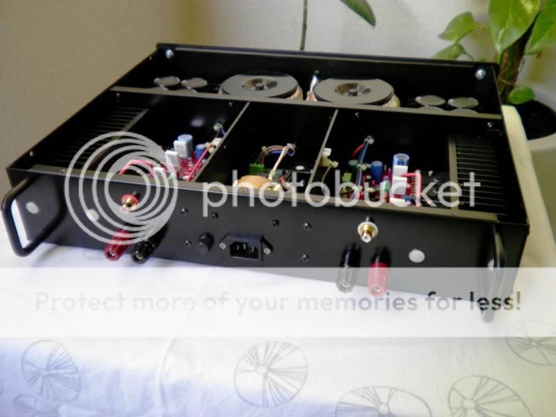
!!Being new to this business of DIY solid state power amps I have little idea of heatsink requirements. [Juni's remarks that his heatsinks are small has reminded me of this fact.]
I have a pair of sinks which are 200mm long, with 40mm fins [including 10mm backplate] and fins on 8mm centres, and 160mm high. Are these adequate for this amp? Or can I reduce the heigth to a more ideal size [as I suspect that too much radiating surface can be detrimental]?
The rest of the case will be made from 7.5mm alloy plate. I intend plenty of ventilation and to place the heatsinks on the external sides. Having plenty of alloy I am considering building the heavy end of a dual mono PS in a seperate chassis.
Lastly, what size transformers will adequately cover the needs for such a supply?
Thank you for any advice you may be able to offer.
Brian, your heatsinks are more than adequate. Any 1 C/W heatsink will do it.
Concerning the transformer: if you plan to build a dual-mono design (like Junie did) I recommend you to use 2 x 25 VAC / 160W.
Else take 1 transformer, 2 x 25 VAC / 250W - 300W. This is what I am using myself.
Best regards - Rudi_Ratlos
Concerning the transformer: if you plan to build a dual-mono design (like Junie did) I recommend you to use 2 x 25 VAC / 160W.
Else take 1 transformer, 2 x 25 VAC / 250W - 300W. This is what I am using myself.
Best regards - Rudi_Ratlos
- Home
- Group Buys
- TO-3 SYMASYM