
Brian,
I didn't offer matched devices (transistors) for the SYMASYM in the past.
What I offered was "hard-to-get" parts, like my favourite DC-blocking capacitor on the input, Vishay's MKT1822 / 10µF, or MPC74 0R22 / 5W resistors.
If you talk about matching the SYMASYM transistors: it is not as essential as you think.
I have once compared my own, highly-matched TO3-SYMASYM to a totally unmatched SYMASYM and could hardly hear any difference.
If you want to match transistors: go and use BJTs for the input differntial pair (f.e. MPSA18, if you do not use a Pre-AMP, or 2N5551, if you use a Pre-AMP)
and match them with your DMM.
Talking about the output-transistors: I recommend you to use NJW0281 / NJW0302.
The OnSemi NJW0 have a very small COB, and - this may answer your question: they have a very small Hfe deviation, when you buy them (from MOUSER for example).
I bought a bulk of 75 pcs. of each several months ago and matched them for some German DIY- friends.
The max. deviation within this bulk has been < 5%!
Best regards - Rudi_Ratlos
P.S. Have a look at my current SYMASYM-build (Post #515). I am using BJTs for the differential input pair.
Yes Mr. Rudi,, I,ve made a number of changes to the circuit..First change r20=22ohm +r19=22ohms change to 47 ohms. this change is good to 45vdc.above this voltage you should put a power diode in series with the resistor. Across the drivers a 100pf cap from base to collector gets rid of any nasty rf garbage. Sit back listen,,check your bias I set mine at about 60ma and adjust to find the sweet spot..ENJOY Regards Evette
An externally hosted image should be here but it was not working when we last tested it.
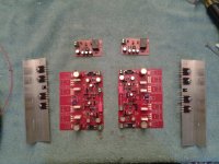
Carl, I received the ordered thermally conductive foil this morning and finished the 1st channel of my SYMASYM.
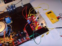
I adjusted the quiescent current / bias to 26mV voltage drop across 2 emitter resistors (between MP1 and MP2).
The DC offset is very, very small (< 1mV).
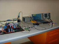
I tested the channel using a 8 Ohm / 80W resistor and played back some sine and square-wave tracks at 16 VAC amplitude. No problem.
If I have some time tomorrow (but I believe that I will receive the FC-100 group-buy PCBs in the morning), I will try and finish the 2nd channel.
What about your build?
Best regards - Rudi_Ratlos
I adjusted the quiescent current / bias to 26mV voltage drop across 2 emitter resistors (between MP1 and MP2).
The DC offset is very, very small (< 1mV).
I tested the channel using a 8 Ohm / 80W resistor and played back some sine and square-wave tracks at 16 VAC amplitude. No problem.
If I have some time tomorrow (but I believe that I will receive the FC-100 group-buy PCBs in the morning), I will try and finish the 2nd channel.
What about your build?
Best regards - Rudi_Ratlos
Attachments
Last edited:
Carl,
you are talking about 2 different things.
I explained in post #450 what to do (which resistor values to use), in case you connect the SYMASYM to a pre-amplifier.
The cap-multiplier has nothing to do with this. It simply "smoothes" the power-rail for the frontend.
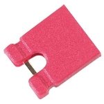
If you do not want to have it this way, just put a shorting bar across Jumper 1 + 2.
Best regards - Rudi
you are talking about 2 different things.
I explained in post #450 what to do (which resistor values to use), in case you connect the SYMASYM to a pre-amplifier.
The cap-multiplier has nothing to do with this. It simply "smoothes" the power-rail for the frontend.
If you do not want to have it this way, just put a shorting bar across Jumper 1 + 2.
Best regards - Rudi
Attachments
OK got it all wired up. One channel checks out and the other channel goes runaway.
One thing I forgot to insulate the bd139. If I fried one of them would that cause a runaway as in the potentiometer does nothing and I measured up to 900 mv before I was able to switch it off.
Ugh...
One thing I forgot to insulate the bd139. If I fried one of them would that cause a runaway as in the potentiometer does nothing and I measured up to 900 mv before I was able to switch it off.
Ugh...
- Home
- Group Buys
- TO-3 SYMASYM