Last week I received the Rudi's boards from Birger. I must say these are very nice and well crafted boards. There is room for improvement however as several components are not labeled at all neither with name nor with value.
Before I go on I have to confess I am a newbee and as Redjr calls it I am a "solder monkee".
Pheeeewwww, now I can start my newbee comments and questions.
On Birgers website there is a link to a Reichelt Bom. This Bom is a shopping cart that describes Reichelt products (with values) and of course doesn't give a clue to the component names. So I started to complete the Bom with component names, because my boards are silkscreened with names and also to get a feeling for the kind of components needed for a build like this. That is a process of cross referencing schematic, my BB's, and Rudi's values silkscreen.
After this job and as even "solder monkees" are entitled to an opinion I vote for a VALUE silkscreen.
Why ?? Because for me it all comes down to getting the correct value at the correct spot on the board. Besides the Bom is also in values.
Of course I agree with Redjr that the value doesn't tell you the whole story. For instance some e-caps are a real puzzle to me. Take for instance the several 100µF caps.
The Bom lists:
RAD FC 100/35 Elko radial, 105°C, low ESR, RM 3,5mm
RAD FC 100/63 Elko radial, 105°C, low ESR, RM 3,5mm
RAD FC 100/50 Elko radial, 105°C, low ESR, RM 5,0mm
These values are meant for the caps C89, 22, 5, 21, 24, 1.
First question: why not keep it simple and use only 63V caps??
Second question: why not all caps in grid 3,5 mm, because as far as I can see the board grid for all the 100µF caps is in fact 3,5 mm ??
Clog,
1st: I tried to do a very compact layout of the "BB-SYMASYM".
2nd: The PCB contains 3 sections: Frontend/Backend of the SYMASYM, PSU and Speaker protection.
The frontend/backend of the SYMASYM requires with 40VDC (at least), 50 VDC (then you are on the safe side anyway) electrolyts.
One exception: the 470µF electrolyt in the NFB-path (C4) need only to be (even <) 16VDC.
The values of the electrolyts of the speaker protection are as shown.
Capacitor C27 should be a 40VDC type (at least), 50VDC to be on the safe side.
What matters as well is the size of the grid of the capacitors.
Concerning the WIMA 100nF film capacitors: the layout is using MKS2- as well as MKS4 - types.
Best regards - Rudi
HiRes Images
Hi,
I was a little bit busy the last days, but finally I cleaned up the values and names layer and created a high resolution PDF. I hope it helps in some way while building the amp.
Symasym-HiRes.pdf
Best regards,
Birger
Hi,
I was a little bit busy the last days, but finally I cleaned up the values and names layer and created a high resolution PDF. I hope it helps in some way while building the amp.
Symasym-HiRes.pdf
Best regards,
Birger
Do any of you clerks know if somebody is selling matched output transistors? Preferably MJL4281A/MJL4302A but other will do")
http://www.diyaudio.com/forums/swap-meet/281693-mjl4281a-mjl4302a-sale-uk.html
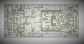
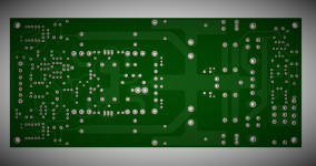
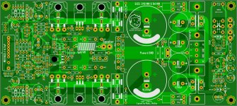
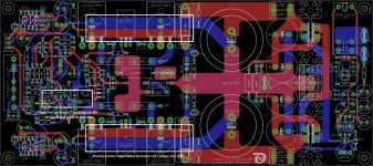
Hello Rudi this is the art work I like the PCB so much that I have to try to make it art work images maybe is not 100% accurate my re-drawing but does look good and I like it a lot
Best Regards
Juan
Best Regards
Juan
Attachments
Last edited:
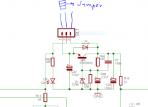
Juan, when a cap is put upon jumper pin2 and pin3, the backend rail-voltage is used as the frontend-voltage.
When the cap is put upon jumper pin2 and pin1, the output voltage of the cap-multiplier ("cap-regulator") is used for the frontend.
Best regards - Rudi
oh ok now I got it Rudi thanks
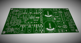
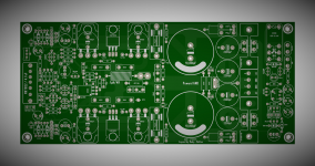
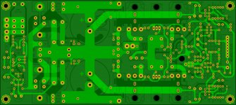
I spend a couple of hours tweaking the layout here is how it look today great PCB design Rudi
Best Regards
Juan
Attachments
Last edited:
Juan, just my "2 cents":
1st cent: keep the backend-rail voltages and GND apart to avoid parasitic capacitances!
2nd cent: keep the frontend's "SmallSignalGND" as small and close / short as possible! Solder a wire manually to connect the "SmallSignalGND" to the "Transformer's GND"!
Your layout looks very, very nice!
I wish you a lot of Brasilian DIYers to use it!
Best regards - Rudi_Ratlos
P.S.: The layout also allows you to use TO264-case transistors like MJL4...
Attachments
Last edited:
Juan, just my "2 cents":
1st cent: keep the backend-rail voltages and GND apart to avoid parasitic capacitances!
2nd cent: keep the frontend's "SmallSignalGND" as small and close / short as possible! Solder a wire manually to connect the "SmallSignalGND" to the "Transformer's GND"!
Your layout looks very, very nice!
I wish you a lot of Brasilian DIYers to use it!
Best regards - Rudi_Ratlos
P.S.: The layout also allows you to use TO264-case transistors like MJL4...
thanks Rudi for the advice but I'm from Puerto Rico and so I'm Puertorrican difficult word to pronounce
jejeje never mind is cool man I will check the distance of backend-rails and to check for TO264 to see if they fit correctly then
good day mister Rudi
Best Regards
Juan
Gentlemen, you can order the "Black Beauty SYMASYM" from:
Symasym Black Beauty | diy-audio-shop.de
Birger (the shop-owner) has 4 PCBs left.
Best regards - Rudi_Ratlos
Symasym Black Beauty | diy-audio-shop.de
Birger (the shop-owner) has 4 PCBs left.
Best regards - Rudi_Ratlos
Trying to order and pay with paypal -
I get this -
Mit Paypal bezahlen. Sollten Sie keinen Paypal-Account besitzen, können Sie auch mit Ihrer Kreditkarte bezahlen.
Sorry I have to try to translate it and see how to pay.
Is there English version of that site ?
Thanks.
Srinath.
I get this -
Mit Paypal bezahlen. Sollten Sie keinen Paypal-Account besitzen, können Sie auch mit Ihrer Kreditkarte bezahlen.
Sorry I have to try to translate it and see how to pay.
Is there English version of that site ?
Thanks.
Srinath.
- Home
- Group Buys
- TO-3 SYMASYM