Rudi,
Should I decide to put a volume control on the amp, what value pot would be the best to use? And should be a log pot? I'm not inclined at this point, but I may want to do it down the road. BTW, I configured the front-end (gain) for use with an active pre that I have too, but I would not use it and a pot together.
Thx,
Rick
Rick, you can of course feed the power for both channels with the same single transformer secondaries.
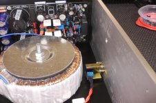
Move your transformer as close as possible to the front of your case (as far as possible away from the SYMASYM frontends).
I do definitely not hear any hum from a build like this.
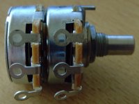
Use a dual log 20K potentiometer for the attenuation.
I have used in the past and have always been content with ALPHA-brand potentiometers. ALPS potentiometers will do it as well.
Best regards - Rudi
Move your transformer as close as possible to the front of your case (as far as possible away from the SYMASYM frontends).
I do definitely not hear any hum from a build like this.
Use a dual log 20K potentiometer for the attenuation.
I have used in the past and have always been content with ALPHA-brand potentiometers. ALPS potentiometers will do it as well.
Best regards - Rudi
Attachments
Rick, you can of course feed the power for both channels with the same single transformer secondaries.
Move your transformer as close as possible to the front of your case (as far as possible away from the SYMASYM frontends).
I do definitely not hear any hum from a build like this.
Use a dual log 20K potentiometer for the attenuation.
I have used in the past and have always been content with ALPHA-brand potentiometers. ALPS potentiometers will do it as well.
Best regards - Rudi
Problem is... That particular case is just not wide enough to accommodate that xformer at the PSU end of the PCBs - only by a few mms. So I moved it as far back (to the front) as it would comfortably fit without touching either of the boards. My mistake for cutting it so close.
 I'll have to wait and see how it sounds after I fire it up in the enclosure. Hopefully, I won't have any issues. Fingers crossed!
 My Asian supplier just started carrying another enclosure that's a full rack-mount width and (I believe) another 'U' higher. But, alas it is much more expensive. Since I already mounted the tranny last night, I'm going to give my current enclosure a go and see if there are any issues. If there are, I'll have to go to Plan B.
Thanks for the info on the pot. I have a couple of ALPS pots in my parts supply should I decide to try one. Not at home, so not sure of the value or type.
BTW, how much max power/channel should I expect with a 400VA 10amp tranny on this build driving 8 Ohm speakers?
Thanks again,
Rick
the power output depends on the sagged supply rail voltage.BTW, how much max power/channel should I expect with a 400VA 10amp tranny on this build driving 8 Ohm speakers?
Thanks again,
Rick
You have not told us what your are doing.
Then work it out from P=Vpk²/2/Rload.
So..... using the formula I get the following;the power output depends on the sagged supply rail voltage.
You have not told us what your are doing.
Then work it out from P=Vpk²/2/Rload.
P = (35 x 35)/2/8
P = 1225/2/8
P = 612.5/8
P = 76.56w
Is my math correct? Vpk = my 35VDC rail voltage (perhaps optimistic), and 8 Ohm my speaker load?
I know there are other factors to consider in the purest evaluation, but all I was after was a ballpark wattage/channel plus/minus 10%.
Rick
Last edited:
if you have +-35Vdc supply rails when the amplifier is at zero output, then expect the supplies to drop significantly when there is a load taking power.
Maybe dropping to +-30Vdc to +-33Vdc.
Then there is a loss through the amplifier. This can be anywhere from 2V to 5v.
That leaves your maximum output at ~33 - (2 to 5) = ~30Vpk
Some models can predict this. But the easiest way is to build and measure.
Maybe dropping to +-30Vdc to +-33Vdc.
Then there is a loss through the amplifier. This can be anywhere from 2V to 5v.
That leaves your maximum output at ~33 - (2 to 5) = ~30Vpk
Some models can predict this. But the easiest way is to build and measure.
if you have +-35Vdc supply rails when the amplifier is at zero output, then expect the supplies to drop significantly when there is a load taking power.
Maybe dropping to +-30Vdc to +-33Vdc.
Then there is a loss through the amplifier. This can be anywhere from 2V to 5v.
That leaves your maximum output at ~33 - (2 to 5) = ~30Vpk
Some models can predict this. But the easiest way is to build and measure.
I'm guessing the rails will only sag dramatically when the current demand of the amp cannot be met comfortably at the supplied voltage and amperage rating of the xformer. At that point the music will be so loud I won't be able to think.
So realistically (and I will measure), the rail voltage - while there might be some minor fluctuations - should remain fairly reliable under normal listening conditions. Given the overall intent (usage) of the amp and type of music I generally listen to. I'm not talking worse case here. Rudi,
Is this amp 'scalable' within a range of voltages - provided the caps along the rails are rated for the max increased voltage? What is the high-end rail voltage this amp was designed for, or can comfortably handle should I want to push the power up some?
Rick
At full power testing there is an easily measureable sag in supply voltage.
I see ~2volts to ~5volts drop in the average voltage on the supply rail. That average does not read the very large increase in ripple on the supply rail. The amplifier output devices do see that ripple. If the ripple increases from 10mVpp when quiescent to 1Vpp when delivering full power than that change from 10mVpp to 1000mVpp becomes an effective (1000-10)/2 drop in voltage that is NOT seen on the average responding voltmeter. Let's assume you have +-59Vdc with 10mVpp ripple, when quiescent.
The minimum voltage seen by the amplifier is 50V-(10mV/2) = 49.995V
Now assuming we lose 4V when reading the average voltage and the ripple increases to 1Vpp while the amp is delivering full power into the rated resistive test load.
The amplifier sees 50-4 -(1000mV/2) = 45.5V
Let's now assume the amp loses 4volts between the supply rail and the peak output at the test load.
Vpk at the test load is now (45.5-4) = 41.5Vpk. That is equivalent to 107.64W into 8r0.
I can confirm that for my builds this is fairly typical.
Had I ignored the supply sag and simply subtracted the Vloss through the amplifier, then the new Vpeak would be 50-4 = 46Vpk. This is equivalent to 132.25W into 8r0.
I doubt anyone can build a 100W amplifier using a 35-0-35Vac transformer that can achieve 132W into 8r0. Ignoring supply sag gives an unreasonably high maximum power prediction.
As an aside, one of our Moderators claims that my supply sag of ~2V to ~5v is unrealistic and he proposed a more typical sag of 16volts for his well engineered builds.
Listening at normal levels of around -20db ref maximum will indeed result is very much lower voltage sags at the supply terminals. This is quite normal. By definition the loud transients are short lived. This results in the capacitor not fully depleting to their fully sagged voltage as in maximum power testing. The audio industry came up with a test to try to replicate this transient reproduction capability. They called it IHF...... and it allowed the less reputable manufacturers to claim enormous power delivery from their amplifiers.
But when we listen to these amps designed specifically to deliver high IHF power, they do not sound as good.
The Symasym works over a surprisingly wide range of supply voltages...............Is this amp 'scalable' within a range of voltages - provided the caps along the rails are rated for the max increased voltage? What is the high-end rail voltage this amp was designed for, or can comfortably handle should I want to push the power up some?.........
I can get a clean sinewave with the supply down at +-3Vdc.
Yes, the maximum output voltage is limited (by the supply rails) to ~1Vac, but it is a clean looking sinewave.
As I increase the supply rails the maximum output scales up accordingly.
I have gone as high as +-52Vdc, with precautions to prevent over-stressing the transistors.
From my experiments the Symasym works from +-3Vdc to +-52Vdc and will work even higher if cascoding of the low power transistors is implemented.
I had cascoded the input LTP for my current 100W into 8r0 builds.
It is finished!
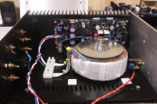
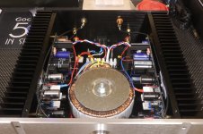
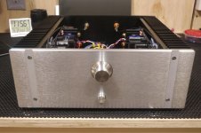
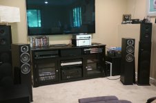
I finished up the internal wiring yesterday and managed to get everything in the enclosure. I'm listening to it now as I write this, and the amp sounds pretty amazing - at least with my modest Energy RC speakers. I'll give it a critical listening test later once I let it break-in a bit. At moderate volume the heatsinks are barely warm. I can't hear any hum whatsoever.
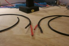
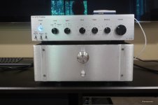
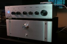
Included a few more pics of the build and internal layout of the enclosure. The last couple pics show it with my Doug Self pre-amp I built a couple of years ago. I configured the front-end of the SymAsym to be used with an active pre so I thought the DS pre would fit the bill nicely. At the moment they seem to go together well. BTW, the volume control is not connected, just covering up a machined hole on the front panel.
Since the PSUs are part of the amp boards, I've kept the signal ground in the domain. Meaning I carried both the input signal and output grounds from RCA to speaker binding posts. Normally, I would tie the input ground and speaker returns to a common or star ground. Essentially I believe I have a floating ground scheme as it is now. The enclosure is earthed at the receptacle, but internal grounds are all floating. I believe I need to tie everything to the case at some point. Yes?
Thanks Rudi for a great project and a wonderful sounding amp - and having the patience during my senior moments. It takes me awhile, but I'm always proud of my results - especially when no magic smoke is released. Also, I'm sure someone will point out that I missed twisting the wires from my tranny. I know, but decided I didn't want to re-work them for such short distance. For those interested, the enclosure I used is this one.
Rick
I finished up the internal wiring yesterday and managed to get everything in the enclosure. I'm listening to it now as I write this, and the amp sounds pretty amazing - at least with my modest Energy RC speakers. I'll give it a critical listening test later once I let it break-in a bit. At moderate volume the heatsinks are barely warm. I can't hear any hum whatsoever.
Included a few more pics of the build and internal layout of the enclosure. The last couple pics show it with my Doug Self pre-amp I built a couple of years ago. I configured the front-end of the SymAsym to be used with an active pre so I thought the DS pre would fit the bill nicely. At the moment they seem to go together well.
BTW, the volume control is not connected, just covering up a machined hole on the front panel. Since the PSUs are part of the amp boards, I've kept the signal ground in the domain. Meaning I carried both the input signal and output grounds from RCA to speaker binding posts. Normally, I would tie the input ground and speaker returns to a common or star ground. Essentially I believe I have a floating ground scheme as it is now. The enclosure is earthed at the receptacle, but internal grounds are all floating. I believe I need to tie everything to the case at some point. Yes?
Thanks Rudi for a great project and a wonderful sounding amp - and having the patience during my senior moments. It takes me awhile, but I'm always proud of my results - especially when no magic smoke is released.
Also, I'm sure someone will point out that I missed twisting the wires from my tranny. I know, but decided I didn't want to re-work them for such short distance. For those interested, the enclosure I used is this one.Rick
Attachments
Last edited:
I noticed over the weekend when I still had the top off that the tranny I'm using has a slight, but noticeable hum to it. It's not a ground loop hum from the speakers, but the tranny itself is humming. For this build I choose a different manufacturer (AVEL-Lindberg) for the tranny. I noticed that it did not have a shield lead that I usually ground on other trannies I have used in the past.
As I also mentioned in the post above the amp is not earthed and probably should be, so when I do that, it may help the hum issue. Will give it a try.
Rick
As I also mentioned in the post above the amp is not earthed and probably should be, so when I do that, it may help the hum issue. Will give it a try.
Rick
Dear TO-3 SYMASYM friends,
one of the buyers of the TO-3 SYMASYM V2 PCBs asked me to offer you the parts that he collected so far for this build.
He himself does not have the time to build this beautiful AMP.
This is what he offers:
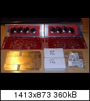
http://www.abload.de/img/to-3symasymaqjjy.jpg
- 2 PCBs TO-3 SYMASYM Version 2
- 1 PCB Power Supply Unit
- 5 pairs of MJ21193G / MJ21194G output transistors (the picture shows only 4 pairs)
- 8 emitter resistors MPC71 0R22 / 5 Watt
- 2 HFe matched pairs MPSA18 input transistors
- 2 ALU - L profiles
All parts are new and have not been used.
The total price will be 65€ (excl. shipping).
Please send me a PM, if you are interested.
Best regards - Rudi

Hello Rudi, could you please reply if is possible to have four of those nice SYMASYM PCB's after my 4-year late discovery?
Thanks, Angelos
Rick, you have built a beautiful piece of work! Looking alone at the RCA-input cables ... ! I appreciate your passion!
I have been using "inexpensive" toroid-transformers (brand: TALEMA) for my builds in the past and have never experienced any transformer-hum!
As Paul stated: maybe you have some DC-offset on any of the outputs (please mesaure DC between GND and output on both channels - short the input during this measurement, please) or:
may it be that your way of using one transformer to drive the backend-PSUs of both channels induces the hum? I don't know!
My current build uses a 4x25VAC toroid, whereas in the past I used a 2x25VAC toroid and 1 (!) PSU-PCB to drive both channels.
I am not an advocate of the "Star-Ground" topology and have never before used it in my builds (I hardly dare to say this).
Connecting ProtectiveEarth of the mains' inlet to the case is the only thing that I do.
I hope (keep my fingers crossed) that you will find the reason of your hum.
Your SYMASYM is worth playing without any hum!
@Tassis: I do not offer TO3-SYMASYM PCBs anymore.
I even do not offer Rick's "BlackBeauty - SYMASYM" - PCBs anymore.
I have grown too old to organize Group-Buys, but ...
I have passed the schematic, the EAGLE-files, the Gerber-files, the Builder's Guide, ... to a young German DIY-friend of mine, Birger is his name, and he will offer you the "BlackBeauty - SYMASYM"
in his German DIY-AUDIO-SHOP by the end of this week (I hope so at least).
I will give you a note as soon as the "BlackBeauty - SYMASYM" is announced in his shop.
Best regards - Rudi_Ratlos
Rudi, Thanks for your kind words. I think at times I'm meticulous to a fault! Always trying to think ahead for any pitfalls I might run into. That generally slows the process down when I'm always in planning mode. As it turned out, the enclosure was just a bit too tight for my liking and I had no other choice but to have the tranny right up against the components on the PCBs. I hope that's not the source of the hum. I usually use toroidal trannies from a local supplier (AnTek) in my neighboring state New Jersey, but this particular size/rating was not available at the time, so it was sourced elsewhere.
Speaking of hum... The hum is ever so slight and with the top on and from my listening position you would never hear it. I just don't know if it's leaking into the signal path per se. I hear absolutely no hum from the speakers.
This was a fun project and helped boost my confidence level with building discrete amp PCBs. I now feel I could tackle any 'difficulty' level of amp. My real forte' however is being the integrator - bringing everything together in a professional way into a nice enclosure with the finishing touches.
Thanks again for the project.
Rick
For months I'm waiting for a chance to buy Rudi's Black Beauties and get my feet wet by building this amp. Just recently I have read that any moment now they will appear in the "diy-audio-shop.de". Yesterday someone in the solid-state section of the forum posted the following question:
Because of my plans to bulid this amp I'm interested what you guys think of his question ??Hi everyone, could I have people's views about Mike B's Symasym. I wish to build a class AB amplifier and remember that a few years ago this amplifier was very well respected by the DIY community.
Is it still regarded this way or has it been superseded by newer / better amplifiers. ( no disrespect Mike )
Clog, Tassis: since yesterday the "Black_Beauty" - SymasymPCBs are available in Birger's German diy-audio-shop.
Symasym Black Beauty | diy-audio-shop.de
Birger sells the PCB for 14.95€ .
The homepage of the German diy-audio-shop is written in German (of course).
But feel free and send Birger an EMail in English to "info@ diy-audio-shop.de", if want want to order.
Best regards - Rudi_Ratlos
Symasym Black Beauty | diy-audio-shop.de
Birger sells the PCB for 14.95€ .
The homepage of the German diy-audio-shop is written in German (of course).
But feel free and send Birger an EMail in English to "info@ diy-audio-shop.de", if want want to order.
Best regards - Rudi_Ratlos
What does the Hum+Noise measure at the speaker terminals?........................Speaking of hum... The hum is ever so slight and with the top on and from my listening position you would never hear it. I just don't know if it's leaking into the signal path per se. I hear absolutely no hum from the speakers.
................
1mVac of H+N is ~-69dB ref 1W
0.1mVac of H+N is ~-89dB ref 1W
- Home
- Group Buys
- TO-3 SYMASYM