Please reply if you find a US source for those pins. I've not seen them in my limited searches at Digikey or Mouser.Great. Thanks. Those I don'the have in my hardware supply so need to order some.")
Thanks,
ryan
RKH,
Try Newark Element 14 for something like these or other sizes,
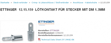
ETTINGER 13.14.229 TERMINAL PIN, 1.3MM DIA, PK100
Cheers
Ryan
I bought 100 from Newark. Let me know many you want and I'll mail them to you. Not sure when they'll arrive. I also bought the matching female connector too. Say $5 for 20?Please reply if you find a US source for those pins. I've not seen them in my limited searches at Digikey or Mouser.
Thanks,
ryan
Rick
I am a bit confused about power specifications of power resistor base stopper R22,24,35,80.
Rudi's Bom shows standard 0.5W while on M Bittner website or P Makura is specified to be 2W.
I have already bought the small powered ones and i dont know what is the real need for this position.
Thanks,
Adrian
Rudi's Bom shows standard 0.5W while on M Bittner website or P Makura is specified to be 2W.
I have already bought the small powered ones and i dont know what is the real need for this position.
Thanks,
Adrian
What is the current rating of your base stopper?
P=I²R therefore I =sqrt(P/R)
The duty cycle is ~50% and the peak value is ~1.4 times the sinewave value, so you can double the current rating for the actual transient peak that is allowed to pass.
eg.
2r2, ½W, metal film, or metal oxide.
I=sqrt(0.5/2.2) = 0.476Amps
The peak transient for base stopper duty would be ~950mApk
That is an enormous base current into the output device !
A driver feeding a 2pr output stage and the driver Re would need to pass >2Apk.
Can your driver do that?
It's not the base stopper you should be asking about, rather it is the Driver temperature de-rated SOAR that is the bigger concern.
Thank you Andrew, knowledgeable as always. Another thing a bit unclear to me is how to choose the value of the volume pot.
In our case Symasym is having aprox 25k input impedance and lets say my signal source (dac) is having about 150ohm output impedance.
Also how a buffer on Symasym input would influence the choice of potentiometre value ?
Adrian
In our case Symasym is having aprox 25k input impedance and lets say my signal source (dac) is having about 150ohm output impedance.
Also how a buffer on Symasym input would influence the choice of potentiometre value ?
Adrian
The Dac is having the classical 3 opamp stage 2is doing the I/V job and the 3-rd buffer.
How to evaluate if he can drive the 10k pot using unbalanced output.
How to evaluate if he can drive the 10k pot using unbalanced output.
An externally hosted image should be here but it was not working when we last tested it.
Balanced output will not work properly with a simple vol pot.
You will have to use the bal to unbal converter to feed the vol pot.
The 4562 should be able to drive the cable, but you will need to check that the capacitance does not interfere with the chip, since I see no isolating resistance.
You will have to use the bal to unbal converter to feed the vol pot.
The 4562 should be able to drive the cable, but you will need to check that the capacitance does not interfere with the chip, since I see no isolating resistance.

I will replace them with some better emitter resistors. I used what i had in my drawer for moment. The problem is that i have already a very good sounding Fc100
Installed sockets for first two transistors to see if there is any difference between mpsa18 , bc550 and sk170 that i have already.
I have received from Reichelt some 8 mm spacers as in your recommended Bom. For what are those spacers , where should be installed?
Sent from my iPad using Tapatalk
Installed sockets for first two transistors to see if there is any difference between mpsa18 , bc550 and sk170 that i have already.
I have received from Reichelt some 8 mm spacers as in your recommended Bom. For what are those spacers , where should be installed?
Sent from my iPad using Tapatalk
Last edited:
Can you please tell us your experiences for this when your tests are made? Would be very interesting for me....to see if there is any difference between mpsa18 , bc550 and sk170 that i have already.
Any conclusions here in the meantime?There are a few Designers that recommend jFETs for the input.
I have never compared a jFET input to a BJT input.
This may turn out to be my first comparison.
Regards,
Chris
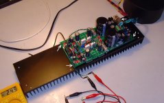
Adrian, the spacers are used to mount the PCB on the heatsink (see the attached image).
When you are done: please do some tests and use 2SK170 and MPSA18 (be aware of the different pinouts of them) as input transistors and give us your impression.
Best regards - Rudi
When you are done: please do some tests and use 2SK170 and MPSA18 (be aware of the different pinouts of them) as input transistors and give us your impression.
Best regards - Rudi
Attachments
Of course i will share my findings with different input transistors but i think it will take some more time.
I am a bit confused about how the "cap multiplier" is working as he is more a regulator that a cap multiplier.
As he has a 36v zenner and i have 35v after rectification he will not be a regulator, it will be just a cap multiplier ? After voltage on regulator input increasing more than 36 v he will work as a regulator ?
Black Beauty v-1 PCB cut.
Hello Rudi. I have bought a pair of BB (first version) pcb.s from a DIY member and looking through the thread I found out that some cut the pcb.c (the psu) some do not. Does it have an impact on the amp performance or is just a matter of in case arrangement? Unfortunately I have not yet received the BOM and Builder Guide, if the guy fails to send them to me would you be so kind to help on the matter?
And let me tell you that the SymAsym Black Beauty pcb.s are realy beautiful. Good job Rudi.
Thanks a lot.
Adrian, the spacers are used to mount the PCB on the heatsink (see the attached image).
When you are done: please do some tests and use 2SK170 and MPSA18 (be aware of the different pinouts of them) as input transistors and give us your impression.
Best regards - Rudi
Hello Rudi. I have bought a pair of BB (first version) pcb.s from a DIY member and looking through the thread I found out that some cut the pcb.c (the psu) some do not. Does it have an impact on the amp performance or is just a matter of in case arrangement? Unfortunately I have not yet received the BOM and Builder Guide, if the guy fails to send them to me would you be so kind to help on the matter?
And let me tell you that the SymAsym Black Beauty pcb.s are realy beautiful. Good job Rudi.
Thanks a lot.
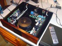
Symasym is coming to life bit by bit.
An externally hosted image should be here but it was not working when we last tested it.
Nice! (frumos
)- Home
- Group Buys
- TO-3 SYMASYM