Andrew, I am currently adjusting the quiescent current on my most recent SYMASYM - TO3-P PCB.
No problem so far.
I am using TO3-P SANKEN 2SC3263 / 2SA1294 as output-transistors.
But - since the SANKENs are very, very fast transistors - in case they show a tendency to oscillate: would you please be so kind and publish your "TOSHIBA" solution?
Best regards - Rudi
P.S.: I am using a 4x25VAC / total rating: 400VA transformer.
Attachments
Last edited:
Hi Andrew,OK.
Have you decided what output devices you propose to use?
Have you decided what voltage you want to run the supply rails at?
I will be using NJW0281G/0302G for the output devices and 35VDC rails as spec'd in Rudi's design.
Rick
I just powered up the second PCB tonight but forgot the two jumpers.
Powered again, this time I noticed I had not plugged in the input LTP .
Powered yet again but this time forgot that without the outputs, I need to place a temporary feedback.
That convinced me I'm not thinking straight so, I'll have another bash tomorrow.
So the components I changed. Pavel's sch has component numbers.
gain 23, r29 = 22k, r30 =1k
added Cherry's 44k || 5uF, the trace on the bottom takes two 1/8th watt 805 22k The 5uF is two 10uF electros and fit on top.
Input filters, c1=1uF (but probably 1u5F later depending on what value r14 zeros the output offset), R13 = 300r, C2=220pF to become 2n2F after testing. R14 = 68k||1M2
VAS Cdom C7 = 47pF in first build, =33pF in the 2nd build to be tested.
CCS LTP R11 = 220r then changed to 200r to get some more current through the VAS LTP. It was too low, only 3.6mA shared between the two sides, now R10 has 401mV indicating 5.89mA or 2.94mA per side.
C6 = 1uF + 1r0
2 output pairs with Re=0r22 (Pavel used 0r15) and biased to 45mV across the test points.
NO, the correct bias does not make it oscillate. I don't understand how Pavel arrived at the underbias to get rid of the oscillation.
split R12 into two. Fitted 15k on the top side and 10k 805 in the trace on the bottom side. I intend to run this on +-42Vdc.
Will add a 120uF later on the top side to improve the filtering of the CCS feed.
C14 tried all the way from 3p3F showing little ripples on sqW, through to 6p8F with tiny ripples. @ 8pF the ripple has completely disappeared. I have not tried 10pF yet, but will do on 2nd build.
1k VR for the multiplier and R24= 470r for the lower leg.
R4 = 4r8 (24r 5off), r22 = 33r, C6 = 100n
R31 & R32 = 47r in 1st and 22r in 2nd.
The 4 HF decoupling are 220nF
The MF decoupling is 1mF & 2m2F
Added diodes output to both supply rails
Added diodes Power Ground to MF decoupling.
Added diodes across R2
I have not fitted any of the PCB cap multipliers yet. May do If I do a separate front end supply and omit R31 & 32
Drivers u$5,6 = mje15032/33 in first build.
Spent yesterday measuring mje 15034 and today measuring mj115035 @ 40mA Ic. Got just 2pairs close in hFE from 33 of each.
Changed the 1st to 34/5 tonight and rechecked the driver current and the Sqw. The drivers now pass 100% and 110% through the base stoppers (3.3mV & 3.0mV) They were about 100:160% using the older devices.
I think that's all I changed.
I have yet tried any output loads, just testing with the Zobel in place so far.
Last edited:
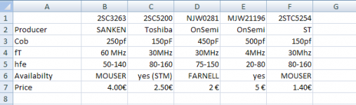
The devices in columns B, C & D are much closer in parameters when you look at the datasheet plots.Andrew, I am currently adjusting the quiescent current on my most recent SYMASYM - TO3-P PCB.
No problem so far.
I am using TO3-P SANKEN 2SC3263 / 2SA1294 as output-transistors.
But - since the SANKENs are very, very fast transistors - in case they show a tendency to oscillate: would you please be so kind and publish your "TOSHIBA" solution?
Best regards - Rudi
P.S.: I am using a 4x25VAC / total rating: 400VA transformer.
The Sanken is NOT twice as fast as the Tosh/Onsemi.
It might be 10% faster if the plots are true representations of typical devices.
2nd Rudi PCB running.
With C7 = 33pF and C14 = 6p8F
I get the oscillation that Pavel described.
Turning down the bias to 20mV across the test points snubs it out.
Changed C7 to 47pF
The bias can be turned a little bit higher before the oscillation comes back on.
Touching the emitter lead of Q9 makes it worse.
Touching the base lead side of c14 makes it much worse.
I will do more later.
Sven, I have sent you an EMail containing the BoM.
The diyaudio-forum has not been accessible to me this morning.
Today is a sad day. I have just ruined my newly built SYMASYM.
I have adjusted it (see my post #1082), connected it to a "substitute - speaker (6R8 at 50W)", looked at its output (sine- and square-wave) on my oscilloscope, found no oscillation, listened to it
(the small TO3-P Sanken sound beautifully), and then turned the music louder.
By some reason or other (maybe I have been distracted) I have only inserted 1.3A fuses into the PCBs' fuse-holders (allthough my transformer is able to provide 4A per secondary).
After some time of playing loud music 2 little clouds of white smoke appeared, then a short bang.
I found out that both fuses have blown.
I am currently not able to re-animate the SYMASYM.
Sad regards - Rudi_Ratlos
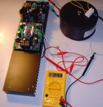
Sven, I have of course replaced the fuses and inserted a 40W light-bulb delimiter into my transformer's primary winding.
The operating voltages (+/-35VDC) are present on the incoming ends of the fuses; the outgoing ends show a voltage of 0V.
No light at all - there is no current flowing anymore.
Funny thing! I will find out.
Optimistic regards - Rudi
The operating voltages (+/-35VDC) are present on the incoming ends of the fuses; the outgoing ends show a voltage of 0V.
No light at all - there is no current flowing anymore.
Funny thing! I will find out.
Optimistic regards - Rudi
I started trouble-shooting my blown SYMASYM today.
The 1st thing I did: I cut through the collector legs of the 4 output-transistors, fitted the light bulb and powered on.
Result: the backend- and frontend - PSU-leds are shining again and there is only very, very little current flowing (the light bulb kept unlit).
Next thing I will try is to play a test-signal and measure the driver's bases and emitters.
Best regards - Rudi_Ratlos
The 1st thing I did: I cut through the collector legs of the 4 output-transistors, fitted the light bulb and powered on.
Result: the backend- and frontend - PSU-leds are shining again
and there is only very, very little current flowing (the light bulb kept unlit).Next thing I will try is to play a test-signal and measure the driver's bases and emitters.
Best regards - Rudi_Ratlos
Attachments
Dear SYMASYM - friends,
regarding my post #1093:
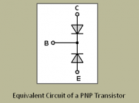
It would have been better to cut through the legs of the Emitter and the Base of each output-transistor to do some sincere transistor measurements.
Please keep in mind the equivalent of a PNP - transistor (for example - see attached image)
Use the diode-test function of your DMM to measure the voltage-drop across the "transistor's diodes" and use the resistance scale (>20K) to measure the leakage current.
But even with my "quick and dirty" procedure as described in post #1093 I found out that one of the two 2SA1294 Sanken PNP-transistors has blown.
I skipped trouble-shooting step #2 (testing the frontend), re-soldered the collector-legs of the other 3 transistors and powered on again.
I am now able again to adjust the quiescent current!
I was lucky things didn't turn out worse, and I am confident to get my SYMASYM playing again.
Best regards - Rudi_Ratlos
regarding my post #1093:
It would have been better to cut through the legs of the Emitter and the Base of each output-transistor to do some sincere transistor measurements.
Please keep in mind the equivalent of a PNP - transistor (for example - see attached image)
Use the diode-test function of your DMM to measure the voltage-drop across the "transistor's diodes" and use the resistance scale (>20K) to measure the leakage current.
But even with my "quick and dirty" procedure as described in post #1093 I found out that one of the two 2SA1294 Sanken PNP-transistors has blown.
I skipped trouble-shooting step #2 (testing the frontend), re-soldered the collector-legs of the other 3 transistors and powered on again.
I am now able again to adjust the quiescent current!
I was lucky things didn't turn out worse, and I am confident to get my SYMASYM playing again.
Best regards - Rudi_Ratlos
Attachments
just lift one end of the base stopper. far cheaper to replace than a damaged transistor.
I suspect sustained oscillation took out the transistor.
Find and cure the oscillation and ripple/overshoot on a sqw.
Then you can go back to testing into reactive loads and then you can connect a speaker.
BTW,
I have a redundant car speaker above the bench. I use a 1k resistor in the feed. Just clip the croc clips to the amplifier to "hear" a low level of the test signal. But, importantly the load is non reactive, except for the cable capacitance after the croc clips. A little 1000r 600mW metal film will take 24Vac at it's max P rating. If you want more, then use a pair of 2k resistors for 34Vac, or three 3k resistors for 44Vac.
Last edited:
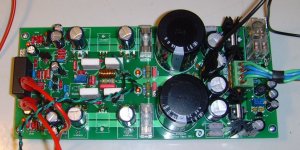
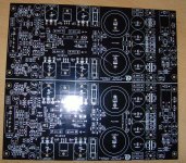
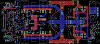
Gentlemen, I have received a couple of requests for my current SYMASYM_BlackBeauty_Rev.2 - PCBs in the past, have ordered the PCBs and received them today (image 1).
I will now ask my German DIY-friend Peter to cut them.
The PCBs' color is black, and the PCBs' quality is very, very good.
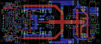
I have reservations for 10 of these lovely PCBs (its layout is shown in image 2), and I have 10 spare PCBs.
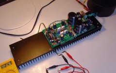
The PCB's size is 211x94mm, and it will fit on a 100mm long heatsink (image 3).
I won't offer any "hard-to-get - components" (for example: matched input differential pair of transistors (2SK170), matched output-transistors, ...) except for the MPC74 - 0R22 Emitter resistors - if you like to have.
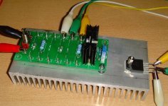
But: I will add a small PCB to match BJT-output - transistors (image 4).
As output-transistors you can use: any ONS TO3-P (f.e. NJW0...) , TO264 (NJW4...), small SANKEN (2SC3263, 2SA1294), ...- I won't recommend to use the TOSHIBA - transistors, .... (have a look at ANDREW.T's posts!).
If you are interested in having a pair of these beautiful SYMASYM - PCBs (including the Builder's Guide, MOUSER BoM, Drill Template, ...):
A pair of these PCBs including the BJT - matching PCB will cost you 29€ (worldwide shipping incl.)
Best regards - Rudi_Ratlos
I will now ask my German DIY-friend Peter to cut them.
The PCBs' color is black, and the PCBs' quality is very, very good.
I have reservations for 10 of these lovely PCBs (its layout is shown in image 2), and I have 10 spare PCBs.
The PCB's size is 211x94mm, and it will fit on a 100mm long heatsink (image 3).
I won't offer any "hard-to-get - components" (for example: matched input differential pair of transistors (2SK170), matched output-transistors, ...) except for the MPC74 - 0R22 Emitter resistors - if you like to have.
But: I will add a small PCB to match BJT-output - transistors (image 4).
As output-transistors you can use: any ONS TO3-P (f.e. NJW0...) , TO264 (NJW4...), small SANKEN (2SC3263, 2SA1294), ...- I won't recommend to use the TOSHIBA - transistors, .... (have a look at ANDREW.T's posts!).
If you are interested in having a pair of these beautiful SYMASYM - PCBs (including the Builder's Guide, MOUSER BoM, Drill Template, ...):
A pair of these PCBs including the BJT - matching PCB will cost you 29€ (worldwide shipping incl.)
Best regards - Rudi_Ratlos
Attachments
- Home
- Group Buys
- TO-3 SYMASYM