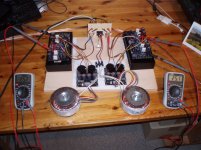
We have lift off
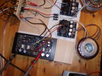
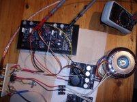
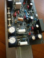
I did wire up the system, and it will remain on the table, to listen some more tomorrow.
Thanks again Rudy, now I don't have to feel sad that I had given my
TO3 build http://www.diyaudio.com/forums/group-buys/187592-3-symasym-71.html#post3488330 away, no I have my own again")
Again(this is the second time, that I find issues looking at the pictures that I do not detect on the real thing) I found a wireing no brainer, I had switched the cinch inputs + and - on both boards which resulted in a loud hum when no music was playing, now with the inputs + and - in the right position, the system is dead silent (you have crawl into the speaker, to detect a light humming)
One channel has spot on 10mV DC offset, the other channel, has about 40 mV offset.
The sound is real good first on, tomorrow I will connect the DDDAC 1794, to do a longer session.
Take your time, recheck every step, and you will have an excellent system.
Grtz
Bert
I did wire up the system, and it will remain on the table, to listen some more tomorrow.
Thanks again Rudy, now I don't have to feel sad that I had given my
TO3 build http://www.diyaudio.com/forums/group-buys/187592-3-symasym-71.html#post3488330 away, no I have my own again
Again(this is the second time, that I find issues looking at the pictures that I do not detect on the real thing) I found a wireing no brainer, I had switched the cinch inputs + and - on both boards which resulted in a loud hum when no music was playing, now with the inputs + and - in the right position, the system is dead silent (you have crawl into the speaker, to detect a light humming)
One channel has spot on 10mV DC offset, the other channel, has about 40 mV offset.
The sound is real good first on, tomorrow I will connect the DDDAC 1794, to do a longer session.
Take your time, recheck every step, and you will have an excellent system.
Grtz
Bert
Attachments
10mV output offset is too much for a Symasym.
Expect <<2mV of output offset for a properly assembled Symasym.
Hi AndrewT,
The aim is to get an output offset below around 50mV DC. So the speakers should be safe.
I have built a few SymAsyms of different kinds, ans as you report, it is possible to get an output offset around zero Vdc.
I mean it is a negative value, that changes about 3mVdc during the time of the measurement, this going up and down ...
So it should be fine to say that a low value is wanted, and that this measurement should be done when the amp is at mostly steady temperature, say after 20 minutes being on. It should be also done reporting the maximum and minimum values that are reached during the measurement. Some multimeters give also these values.
The work done by our friend Watchmouse is IMHO good
and he should be able to fully enjoy the outstanding sound produced by the SymAsyms that he did build .Have a nice day AndrewT
,Best regards
rephil
Anybody in need of a Preamp? As I never finished and no longer need my VCPre (sorry Rudi) I am selling mine.
Included would be the
- VCPre PCB
- 2x16 Char LCD, soldered to the LCD auxilliary PCB
- Motor Potentiometer (will have to look up the brand, but it was the one Rudi recommended)
- IR Receiver and temperature ICs
- Cable housings to complete the cables for the VCPre
You would only need the LDRs to complete it.
If anybody is interested, just contact me and we will a suitable price.
Regards,
Fabian
Currently on hold. Not selling it until the buyer wants to debug itself.
Regards,
Fabian
I was not able to do a new listening session.
And it will be a few weeks before, I am able to update my findings, Andrew and Rephil thanks for the comments, I will do some checking into the DC offsets of other SYMASYM builds that I have access to in due time.
Grtz Bert
The sound is real good first on, tomorrow I will connect the DDDAC 1794, to do a longer session.
And it will be a few weeks before, I am able to update my findings, Andrew and Rephil thanks for the comments, I will do some checking into the DC offsets of other SYMASYM builds that I have access to in due time.
Grtz Bert
Hi,
Unfortunately I couldn't pursue the building of my amplifier for some time.
Right now I am back again and want to start ordering the parts.
Some questions :
-Are these heatsinks appropriate if I take one for each channel :
https://www.reichelt.de/V-6506G/3/i...46&ARTICLE=22272&artnr=V+6506G&SEARCH=V+6506G
-Where can I order a transformer which fits the build with 2 channels + 1PSU
Greets
TrustinTech
Currently on hold. Not selling it until the buyer wants to debug itself.
Regards,
Fabian
Update: Project debugged, "finished" (LDRs still needed) and tested. On sale, see here:
http://www.diyaudio.com/forums/swap...fier-kit-partially-assembled.html#post4092342
Regards,
Fabian
he is back
Hi Andrew, right the other symasym builds have lower DC offsets, still this system sounds just as wonderful as the previous TO3 symasym together with the DDDac 1794
From the various docs/build guides, I read that a DC offset below 10 mV is excellent, as long as the value is below 50 mV all seems good.
Happy listening
Bert
10mV output offset is too much for a Symasym.
Expect <<2mV of output offset for a properly assembled Symasym.
Hi Andrew, right the other symasym builds have lower DC offsets, still this system sounds just as wonderful as the previous TO3 symasym together with the DDDac 1794
From the various docs/build guides, I read that a DC offset below 10 mV is excellent, as long as the value is below 50 mV all seems good.
Happy listening
Bert
Is it overkill to use two 300va transformers for a dual setup? Any adjustment to make use the best of these transformers, considering my heatsinks are large enough.
In my current build, I have 2, 2x 25 V, 230 VA transformers this gives me a nice sound. I have made no special provisions in using these transformers.
Grtz
Bert
Thanks Rudi, I've never fussed too much on the type of capacitor to use in a zobel, but i was just checking in case someone had experimented on this item in the Symasym.
The build is coming along nicely.
I have a couple of random observations.
I really like the fuseholders in the Reichelt BOM .There's a touch of class about them . They come with covers which is even more cool.
I found a solution to the problem of quickly reaching the solder melting point when attaching a component where there is a big copper trace taking away the heat as in the power supply PCB . Tonight I used two soldering irons with the pretinned tips simultaneously touching the component lead and the pad on the PCB. The solder melts very quickly .
It may be that the heating element in my Hakko isn't performing , but even when it was new, soldering a piece to a thick wide copper trace always took a while to generate enough heat , but with two irons at the same time its much quicker.
Maybe someone is looking for ...
http://www.diyaudio.com/forums/swap...amplifier-symasym-to264-made-rudi-ratlos.html
http://www.diyaudio.com/forums/swap...amplifier-symasym-to264-made-rudi-ratlos.html
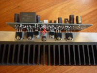
Some pics of 1st of 4 boards. I went slowly, cross referencing Rudi's excellent instructions, pcb and circuit diagrams.
The PCB is a pleasure to work with . I don't know if I imagined this, but the flux comes off more easily from the black mask with the methylated spirits.
I tried hard to fit the semis onto a flat backed heatsink but in the end I went with one of these so that I could more easily fit the legs of the 15030/1 and BD139
http:////www.conradheatsinks.com/products/single_f.html
5mv of DC offset with 22mv across the measuring points 1 and 2 .
Attachments
- Home
- Group Buys
- TO-3 SYMASYM