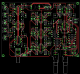
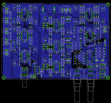
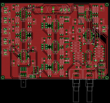
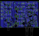
Well here's another update:
-I have ordered all the components, they should arrive today or tomorrow. This means I can test the sensing circuit soon (probably in the coming week).
-Discovered a stupid mistake in the schematics of the equalizer sections; fixed it.
-Added the option to put 2 small capacitors in parallel for C502, C512 and C522 of the equalizer sections. After some calculations I came to the conclusion that the ratio between the capacitors in the EQ sections is purely dependant on the desired Q, resulting in many cases in non standard values for either one of them. Now you can combine 2 capacitors in parallel to come to those non standard values (can only be done with small valued caps: so mind your footprint! Small value caps will also result in higher value resistors).
-Then sort of a question: Because this is my first more complicated PCB design, I am still learning about grounding techniques and so on. The current design has a ground pour in both layers. I believe the general consensus is that a ground pour in the bottom layer and signal traces in the top layer is the most desirable situation when having a 2 layer board. With a design like this, this will automatically result in some signal traces ending up in the bottom layer between the ground pour. I am now doing a quick redesign to see how much traces will end up there if I would set up the board like this.
Any of you guys have an idea what the best solution would be? At how many traces in the ground layer you decide: it's better to have 2 ground pours? (I will upload the two options after this weekend, so you can have a look)
-Current interest is now: minimum of 45 boards, maximum of 52 boards. This brings the pricing down to about € 7,50 per board.
Thanks for the compliment . Payments will indeed be done via Paypal. I will get a more precise estimate for the board price in the coming week. By the end of next week I will ask everybody to make their final interest known. Then I will give details on the order proces as well.
That's around $ 7,40.
-I have ordered all the components, they should arrive today or tomorrow. This means I can test the sensing circuit soon (probably in the coming week).
-Discovered a stupid mistake in the schematics of the equalizer sections; fixed it.
-Added the option to put 2 small capacitors in parallel for C502, C512 and C522 of the equalizer sections. After some calculations I came to the conclusion that the ratio between the capacitors in the EQ sections is purely dependant on the desired Q, resulting in many cases in non standard values for either one of them. Now you can combine 2 capacitors in parallel to come to those non standard values (can only be done with small valued caps: so mind your footprint! Small value caps will also result in higher value resistors).
-Then sort of a question: Because this is my first more complicated PCB design, I am still learning about grounding techniques and so on. The current design has a ground pour in both layers. I believe the general consensus is that a ground pour in the bottom layer and signal traces in the top layer is the most desirable situation when having a 2 layer board. With a design like this, this will automatically result in some signal traces ending up in the bottom layer between the ground pour. I am now doing a quick redesign to see how much traces will end up there if I would set up the board like this.
Any of you guys have an idea what the best solution would be? At how many traces in the ground layer you decide: it's better to have 2 ground pours? (I will upload the two options after this weekend, so you can have a look)
-Current interest is now: minimum of 45 boards, maximum of 52 boards. This brings the pricing down to about € 7,50 per board.
Well... I sent you a PM telling you that I have bought MiniDSP instead. Now that I have looked at your fine work I can't resist buying one.
1 board for me
I suppose payments are done with Paypal ?
Thanks for the compliment
Actually I think I will up my order to two boards.Whats 5.70 euro's translate into US $?
That's around $ 7,40.
UPDATE!
-Checked the schematics.
-Did some updates on some of the routing.
-Tried adding option for Alpha RV120 pots: failed. These Alpha pots use 3.75 mm spacing with the same pin to PCB edge spacing as the Bourns, while the Bourns pot uses 2.5mm spacing. This results in overlapping vias and very close drill distances. So I'll leave the PCB for the Bourns option (unless the majority protests in favor of the Alpha option).
-Build a breadboard version of the sensing circuit. I'll hook it up and test it later this week. I will also try to post some component values together with their release times.
-Made a version with only a single bottom ground pour:
Single ground pour version:


Double ground pour version:


Any comments yet on the 'best' solution? Or should I post it on a 'PCB design' forum?
-Checked the schematics.
-Did some updates on some of the routing.
-Tried adding option for Alpha RV120 pots: failed. These Alpha pots use 3.75 mm spacing with the same pin to PCB edge spacing as the Bourns, while the Bourns pot uses 2.5mm spacing. This results in overlapping vias and very close drill distances. So I'll leave the PCB for the Bourns option (unless the majority protests in favor of the Alpha option).
-Build a breadboard version of the sensing circuit. I'll hook it up and test it later this week. I will also try to post some component values together with their release times.
-Made a version with only a single bottom ground pour:
Single ground pour version:


Double ground pour version:


Any comments yet on the 'best' solution? Or should I post it on a 'PCB design' forum?
Hello, back again with another update.
-I tested the sensing circuit on breadboard and have some release times for several capacitor, resistor combinations:
47uF + 5Mohm = 8 minutes
47uF + 2Mohm = 3 minutes
68uF + 5Mohm = 10 minutes
68uF + 2Mohm = 4 minutes
This should help you get on your way and make it easy to estimate some other values. Keep in mind however that this was done on a breadboard and could be a little different when used on the PCB.
-I changed the design so that the sensing circuit has its own ground plane. This can be connected to the rest of the ground via a small valued resistor or jumper. This makes it also possible to connect it to a star ground point off board. This configuration should make it somewhat easier to solve ground loop problems should they arise in your situation.
-Today I will send PM's to all the people who did not decide yet how many PCB's they want.
-I will post instructions on payment later today or tomorrow and then give everybody untill the end of next week or so to send in payments. Then I can send in the order by the end of next week. I don't exactly know how long it will take to get the order in, but I expect 2 to 3 weeks (if customs is willing to cooperate). Then a few days to prepare all your seperate packages and get them in the mail.
-I tested the sensing circuit on breadboard and have some release times for several capacitor, resistor combinations:
47uF + 5Mohm = 8 minutes
47uF + 2Mohm = 3 minutes
68uF + 5Mohm = 10 minutes
68uF + 2Mohm = 4 minutes
This should help you get on your way and make it easy to estimate some other values. Keep in mind however that this was done on a breadboard and could be a little different when used on the PCB.
-I changed the design so that the sensing circuit has its own ground plane. This can be connected to the rest of the ground via a small valued resistor or jumper. This makes it also possible to connect it to a star ground point off board. This configuration should make it somewhat easier to solve ground loop problems should they arise in your situation.
-Today I will send PM's to all the people who did not decide yet how many PCB's they want.
I'm interested in 2 boards. When you plan to finalize the project so far?
Vlad.
-I will post instructions on payment later today or tomorrow and then give everybody untill the end of next week or so to send in payments. Then I can send in the order by the end of next week. I don't exactly know how long it will take to get the order in, but I expect 2 to 3 weeks (if customs is willing to cooperate). Then a few days to prepare all your seperate packages and get them in the mail.
Pricing, payment & shipping info!
Dear all,
Here is some final information:
-The board: FR4, 2-layer, 140mmx100mm, 2.0mm thickness, 70um copper, immersion gold finish, black soldermask
-Pricing: € 7,50 per board (the few boards more or less from people who don't know their final amount yet, doesn't do much with the price). If there's money left (a maximum of € 25,- or so if all order their maximum amount) will go to diyAudio.com.
-Shipping costs:
Countries in Europe:
1 board: € 2,55
2-3 boards: € 3,40
4-6 boards: € 6,80
Other countries:
1 board: € 2,85
2-3 boards: € 5,70
4-6 boards: € 10,45
European Countries for the Dutch postal services: Albania, Andorra, Belgium, Bosnia-Herzegovina, Bulgary, Canary Islands, Cyprus, Denemark, Germany, Estonia, Faeröer Islands, Finland, France (including Corsica and Monaco), Gibraltar, Greece, Greenland, Hungary, Ireland, Iceland, Italy, Channel Islands, Croatia, Latvia, Liechtenstein, Lithuania, Luxemburg, Macedonia, Malta, Moldavia, Montenegro, Norway, Ukrain, Austria, Poland, Portugal (including Azores and Madeira), Roemenia, Russia (including Aziatic part), San Marino, Serbia, Slovenia, Slovakia, Spain (including Balearic Islands), Tsjech Republic, Turkey (including Aziatic part), Vatican City, United Kingdom, White Russia, Sweden, Switserland.
-Ordering: send me a PM with the following details: your full name, your address (including zip code and country information), the number of boards you want (I expect this to be the same as your expressed interest ) and your calculated total price ([number of boards] x € 7,50 + shipping costs) and a working email address.
-Payment: after sending met the PM with your details, you can send payment to the following Paypal account: m_flinkenfloegel[at]hotmail[dot]com. Do not forget to MENTION YOUR DIYAUDIO MEMBER NAME and the amount of boards with the payment! That will make keeping track of the payments a lot easier. This is a 'personal' Paypal account so I think it will cost you a fee if you pay by credit card. If you decide to pay by credit card: pay the fee yourself! This is not calculated in the price.
-Timeline: Please send me your PM and payment before the 8th of April. This should be sufficient time for everybody. I will then send out the order in the second week of April.
I will post the final iteration of the schematic (there have been some changes since I last posted it (removed some errors and made some additions) and the final versions of the layers and an updated BOM.
If you have any questions; feel free to ask.
Maarten
Dear all,
Here is some final information:
-The board: FR4, 2-layer, 140mmx100mm, 2.0mm thickness, 70um copper, immersion gold finish, black soldermask
-Pricing: € 7,50 per board (the few boards more or less from people who don't know their final amount yet, doesn't do much with the price). If there's money left (a maximum of € 25,- or so if all order their maximum amount) will go to diyAudio.com.
-Shipping costs:
Countries in Europe:
1 board: € 2,55
2-3 boards: € 3,40
4-6 boards: € 6,80
Other countries:
1 board: € 2,85
2-3 boards: € 5,70
4-6 boards: € 10,45
European Countries for the Dutch postal services: Albania, Andorra, Belgium, Bosnia-Herzegovina, Bulgary, Canary Islands, Cyprus, Denemark, Germany, Estonia, Faeröer Islands, Finland, France (including Corsica and Monaco), Gibraltar, Greece, Greenland, Hungary, Ireland, Iceland, Italy, Channel Islands, Croatia, Latvia, Liechtenstein, Lithuania, Luxemburg, Macedonia, Malta, Moldavia, Montenegro, Norway, Ukrain, Austria, Poland, Portugal (including Azores and Madeira), Roemenia, Russia (including Aziatic part), San Marino, Serbia, Slovenia, Slovakia, Spain (including Balearic Islands), Tsjech Republic, Turkey (including Aziatic part), Vatican City, United Kingdom, White Russia, Sweden, Switserland.
-Ordering: send me a PM with the following details: your full name, your address (including zip code and country information), the number of boards you want (I expect this to be the same as your expressed interest
-Payment: after sending met the PM with your details, you can send payment to the following Paypal account: m_flinkenfloegel[at]hotmail[dot]com. Do not forget to MENTION YOUR DIYAUDIO MEMBER NAME and the amount of boards with the payment! That will make keeping track of the payments a lot easier. This is a 'personal' Paypal account so I think it will cost you a fee if you pay by credit card. If you decide to pay by credit card: pay the fee yourself! This is not calculated in the price.
-Timeline: Please send me your PM and payment before the 8th of April. This should be sufficient time for everybody. I will then send out the order in the second week of April.
I will post the final iteration of the schematic (there have been some changes since I last posted it (removed some errors and made some additions) and the final versions of the layers and an updated BOM.
If you have any questions; feel free to ask.
Maarten
- Status
- This old topic is closed. If you want to reopen this topic, contact a moderator using the "Report Post" button.
- Home
- Group Buys
- Subwoofer Filter PCB with LFE sensing, EQ sections, 12/24 dB LR cutoff