BOM, etc. is in post #70...just sayin'
http://www.diyaudio.com/forums/grou...ections-12-24-db-lr-cutoff-4.html#post2977562
http://www.diyaudio.com/forums/grou...ections-12-24-db-lr-cutoff-4.html#post2977562
Well, dropped all envelopes at the post office this morning. Let's hope shipping goes smoothly without incidents or extremely long customs hold-ups.
One remark about soldering:
I've come to the conclusion that the connections between the ground pads and ground pour are too large. This results in a very good heat transfer from your soldering iron to the ground plane. So it will take a while before the pad is heated up sufficiently. Please keep this in mind when soldering pads connected to the ground layer. Otherwise you could end up with several cold solder joints. These pads are easily identified: your solder will not flow immediately around these pads...
I have tried to solder to a ground plane.
I have tried to solder to a pad that has thermal resistance bridges to the surrounding ground plane.
Both situations have issues.
I normally solder with 63/37 at ~300°C.
For large pour connections with resistance bridges I increase my iron to ~350°C to enable fairly quick soldering times and add a clip on sink to the semiconductor lead on the other side.
For a full plane connection, I go to ~400°C with the same clip on protection.
Do not even consider using any of the higher temperature solders !!!!!!!!!!!
clip on protection
Very wise remark!
Fortunately the only IC's with a direct ground connection are leg 3 from the Mosfet and the minus leg of IC4 (opamp for switch). All the others are all resistors, capacitors or connectors. These should be a little more resistant to overheating.
Lesson learned though: Next time I do a design, I'll implement smaller thermal relief connections between the pads and the polygon...
Got my two boards, thanks! 
An externally hosted image should be here but it was not working when we last tested it.
An externally hosted image should be here but it was not working when we last tested it.
Last edited:
You're all very welcome  .
.
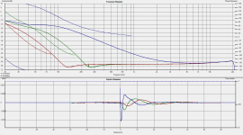
Drove some signals through te board yesterday, that part of the board seems to be working as advertised (frequency control, 12/24 dB switch, phase switch, phase control):

I haven't got the LFE circuit working yet though. Have to check the components. It worked on breadboard, so don't see any reason why it shouldn't work now. Keep you posted.
Drove some signals through te board yesterday, that part of the board seems to be working as advertised (frequency control, 12/24 dB switch, phase switch, phase control):

I haven't got the LFE circuit working yet though. Have to check the components. It worked on breadboard, so don't see any reason why it shouldn't work now. Keep you posted.
I've been overly ambitious...can't find the time or funds for this project too.
I've got two boards(untouched) if anyone who missed this groupbuy is interested send me a PM. All I want is what I paid for the boards plus shipping(actual cost from Sweden to where you might be) and the buyer pays the paypal fees.
I've got two boards(untouched) if anyone who missed this groupbuy is interested send me a PM. All I want is what I paid for the boards plus shipping(actual cost from Sweden to where you might be) and the buyer pays the paypal fees.
- Status
- This old topic is closed. If you want to reopen this topic, contact a moderator using the "Report Post" button.
- Home
- Group Buys
- Subwoofer Filter PCB with LFE sensing, EQ sections, 12/24 dB LR cutoff