And, for your amusement, a Texas Inst. P8002 power JFET from 30 years ago.
They would never admit their parenthood today.
It has the same package as a BD139 or such. There was the P8000 also in TO220.
They then were the holy grail in shortwave receivers as 50 Ohms termination
of ring mixers. 20mA di / 1V dv seems to fit.
They would never admit their parenthood today.
It has the same package as a BD139 or such. There was the P8000 also in TO220.
They then were the holy grail in shortwave receivers as 50 Ohms termination
of ring mixers. 20mA di / 1V dv seems to fit.
Attachments
Last edited:
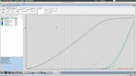
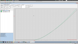
Occasionally I get unexpectedly screwy I-V curves from my Locky-Z, that can be made normal again by installing anti-oscillation capacitors across various pins. Since the display is not a real time oscilloscope, oscillatory "fuzz" is not visible. And averaging the results with "AD_Samples=N" attenuates this further.
Are you trying to derive models or just match pairs etc? When I had to set up to match pairs for Spectral production many years ago the simplest was to set up the operating conditions for the fets using an opamp to set them as current sources and then measure the gate voltage at the target current. Its very simple and works quite well.
If you are sorting for noise you could add the cascode to define the drain voltage and measure the noise across the load resistor at critical frequencies (Quan-tech style) or just look at the spectrum. I once used an LED spectrum analyzer ('80s style) I picked up from a thrift store for a readout. This doesn't necessary tell you the GM but adding a small tone at the input would on the fft or readout.
If you are sorting for noise you could add the cascode to define the drain voltage and measure the noise across the load resistor at critical frequencies (Quan-tech style) or just look at the spectrum. I once used an LED spectrum analyzer ('80s style) I picked up from a thrift store for a readout. This doesn't necessary tell you the GM but adding a small tone at the input would on the fft or readout.
Are you trying to derive models or just match pairs etc? When I had to set up to match pairs for Spectral production many years ago the simplest was to set up the operating conditions for the fets using an opamp to set them as current sources and then measure the gate voltage at the target current. Its very simple and works quite well.
At least I can check if the models available behave similar
to the real thing. The IF3601/3602 cannot be represented by a single model,
it strays just too much.
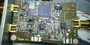
They would also have to be selected in real life. For example, paralleling Q2 and Q7
in the picture above would not make any sense with only one bias servo: at -0.7V bias,
Q7.123 and Q7.567 would carry all the current; Q2.123 and Q2.567 would carry nothing
at all, they do not increase gm and would only double the capacitance. That would
make the noise worse and not better, at €50 extra.
BF862 OTOH can simply be paralleled, they are quite uniform.
If you are sorting for noise you could add the cascode to define the drain voltage and measure the noise across the load resistor at critical frequencies (Quan-tech style) or just look at the spectrum. I once used an LED spectrum analyzer ('80s style) I picked up from a thrift store for a readout. This doesn't necessary tell you the GM but adding a small tone at the input would on the fft or readout.
I can measure the noise of the amplifier directly with the 89441A vector
signal analyzer and compare it to the noise of a 60 Ohm resistor (1nV/rtHz).
You don't even have to know the gain precisely.
Does anybody know if the Locky-Z makes pulse measurements or if it
just cranks up the current with 100% duty cycle? That would distort the curves
because of thermal effects.
@ Mark: yes, oscillations might be a problem.
Does anybody know if the Locky-Z makes pulse measurements or if it
just cranks up the current with 100% duty cycle? That would distort the curves
because of thermal effects
.
Not pulsed. So thermal effects and the stability of the connectors account for most of the variations i came across. The unit needs to stabilise for about 3-4 mins after switch on. Measuring a fixed resistor across DS (CE) using the locky_z did a lot for my sanity...
Another question for the participants in this good S/N thread:
Is there any data on the noise behavior of analog switches when
used as choppers? I think at ADG819 and such. Is there more
than the thermal noise from the channel resistance or are there
other effects via charge injection or whatever?
The ADG819 goes down to 0.5 Ohm resistance. Are there 1/f surprises?
I'd like to use a 1 MHz chopping frequency, have build a breadboard
but there are still nasty switching spikes at the transformers.
regards, Gerhard
Law of the conservation of spikes:
Decouplers will convert voltage spikes to current spikes.")
Is there any data on the noise behavior of analog switches when
used as choppers? I think at ADG819 and such. Is there more
than the thermal noise from the channel resistance or are there
other effects via charge injection or whatever?
The ADG819 goes down to 0.5 Ohm resistance. Are there 1/f surprises?
I'd like to use a 1 MHz chopping frequency, have build a breadboard
but there are still nasty switching spikes at the transformers.
regards, Gerhard
Law of the conservation of spikes:
Decouplers will convert voltage spikes to current spikes.
Choppers have been built with cdse photocells even and worked at microvolt levels with very low noise. The Keithley and Fluke null detectors would be a good place to look as well as the sota chopper stabilized opamps. The chopper noise is still there and 1 Mhz switching may not leave enough time for the switches to settle. I think the fastest I have seen is in the 50 KHz range.
A synchronous rectifier solution lifted from a switching converter would be a good starting point.
A synchronous rectifier solution lifted from a switching converter would be a good starting point.
Oh, I have really tiny transformers, like Digikey 553-2287-1-ND.
CX2049LNLT by Pulse Engineering.
I use the core and the mounting plate only, had to rewind them under the microscope
Schnaps and/or beta blockers might help.
The transformers go up to 500 MHz, some others that I have here go even higher.
I have reduced the speed to 500 KHz, that is already at the lower frequency corner.
I also use the clock to generate VCC/VEE for the analog switches, not much current needed. The input floats completely at baseband, just a few pF coupling to the universe.
Scott's optocouplers might work also for the power supply, with less RF involved.
Gonna check that.
I want pV, not uV.
Last edited:
The Keithley and Fluke null detectors would be a good place to look as well as the sota chopper stabilized opamps.
Unfortunately I can find nothing on this but apparently it is possible to get an ENR of 1 Ohm.
http://www.emelectronics.co.uk/p13.html
There seems to be a funny effect that MOSFETs don't have full
1/f noise unless they have been on for some time.
That is not the intended mode of the chopper, but could be
a pleasant 2nd order effect.
< https://ris.utwente.nl/ws/portalfiles/portal/5337827 >
BTW my chopper does not work like most integrated choppers
via offset correction; I just chop the input, transform upwards
with 1:32 turns, amplify another 40 dB and unchop again
with the same clock, optionally shifted by n*5 nsec to make up
for the amplifier delay. That is done in a small CPLD, so I'm
flexible in the choice of frequencies.
There is no global feedback, must sound really good!
I have played again with the chopper. Spent 3 hours last night on the
secondary of the input transformer. I gave up after 52 turns of 50 um CuL wire.
The wire would always turn into a knot or break with just a little bit too much force
Unfortunately it turned out that my FFT analyzer is limiting me at these low frequencies.
I cannot turn up the preamp gain further without overdriving it. The noise of the
analyzer does not come from the input; it stays the same between short & open.
I think it comes from its synthesizer; it is made to check complicated modulations
at up to 2.7 GHz.
Any ideas of FFT analyzers that shine @ < 100 Hz???
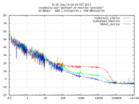
Nevertheless, here are first results. The upper frequency corner is determined
by a MFB low pass at 15 KHz or so, that is arbitrary, I wanted to make sure that
nothing of the 500 KHz chopping clock comes through.
The blue line is just the Agilent 89441A analyzer with a short on its input. That
is currently my measurement limit.
The green line is the chopper amplifier with its input shorted, the red line is the
noise of a 15 Ohm resistor on the input. 15 Ohm is abt. 500pV/rtHz.
The amplifier is 10 dB quieter, that should be near 150 pV/rtHz. I think
this is not yet the limit. More turns on the secondary or paralleling the
first ADA4898 might help. Also the ADG819 FET switches have half
an Ohm, there are 2 of them in series on the input side. Replicating
them should help a little, but not on a home-etched board.
The input is differential and floating; power, clock and signal
go through transformers. Power is the rectified clock, just 2 Schottkies
and caps for +/- 2.4V. The ADG819 needs only symbolic Vdd/Vss.
The absolute values given in the title of the plot do not apply,
only relative dB.
I must find someone locally here who has a better FFT analyzer.
regards, Gerhard
secondary of the input transformer. I gave up after 52 turns of 50 um CuL wire.
The wire would always turn into a knot or break with just a little bit too much force
Unfortunately it turned out that my FFT analyzer is limiting me at these low frequencies.
I cannot turn up the preamp gain further without overdriving it. The noise of the
analyzer does not come from the input; it stays the same between short & open.
I think it comes from its synthesizer; it is made to check complicated modulations
at up to 2.7 GHz.
Any ideas of FFT analyzers that shine @ < 100 Hz???
Nevertheless, here are first results. The upper frequency corner is determined
by a MFB low pass at 15 KHz or so, that is arbitrary, I wanted to make sure that
nothing of the 500 KHz chopping clock comes through.
The blue line is just the Agilent 89441A analyzer with a short on its input. That
is currently my measurement limit.
The green line is the chopper amplifier with its input shorted, the red line is the
noise of a 15 Ohm resistor on the input. 15 Ohm is abt. 500pV/rtHz.
The amplifier is 10 dB quieter, that should be near 150 pV/rtHz. I think
this is not yet the limit. More turns on the secondary or paralleling the
first ADA4898 might help. Also the ADG819 FET switches have half
an Ohm, there are 2 of them in series on the input side. Replicating
them should help a little, but not on a home-etched board.
The input is differential and floating; power, clock and signal
go through transformers. Power is the rectified clock, just 2 Schottkies
and caps for +/- 2.4V. The ADG819 needs only symbolic Vdd/Vss.
The absolute values given in the title of the plot do not apply,
only relative dB.
I must find someone locally here who has a better FFT analyzer.
regards, Gerhard
Attachments
Last edited:
Great work, Gerhard! You have my full sympathies on trying to work with 50 um wire -- much of my grad degree had me hand-building my apparatuses with 80 or 100 um Pt wire, which is pretty much the same mechanical strength as Cu.
One thing I found to help was to put kapton tape on the plier faces to soften the edges (greatly reduced breakage when trying to pull tension). Also you have to always draw it straight off the spool, which I'd do with my fingers (in gloves, of course) in order to not get loops to form, which look like knots and snap under tension.
One thing I found to help was to put kapton tape on the plier faces to soften the edges (greatly reduced breakage when trying to pull tension). Also you have to always draw it straight off the spool, which I'd do with my fingers (in gloves, of course) in order to not get loops to form, which look like knots and snap under tension.
I have not seen Wayn's World, but I have seen Alice Cooper this summer
@ the Wacken heavy metal festival. The driving force behind that was my
16yo daughter who must not go there alone, per order of la mama.
The weather was very mixed, sun but also a deluge, that transformed
the place into a swamp. That has some tradition there, year for year.
They are working on it, this year with some drainage and a beer pipeline
so they do not need as many trucks on the campus.
We were lucky to get a tent site up on a hill
It was very peaceful, the true summer-of-love-mood from 68. The
only noted police action was a case of loud nightly music on a camp
site. They did nothing against it, of course.
With a festival nearly a week long and half a dozen of stages, the
performances must be mixed, but AC stood out even under the top acts.
He must be well over 70 by now, but still full of energy. He even played
Pink Floyd and The Ace Of Spades for Lemmy with a chorus
of 75,000. That really did have some magic.
@ the Wacken heavy metal festival. The driving force behind that was my
16yo daughter who must not go there alone, per order of la mama
.The weather was very mixed, sun but also a deluge, that transformed
the place into a swamp. That has some tradition there, year for year.
They are working on it, this year with some drainage and a beer pipeline
so they do not need as many trucks on the campus.
We were lucky to get a tent site up on a hill
It was very peaceful, the true summer-of-love-mood from 68. The
only noted police action was a case of loud nightly music on a camp
site. They did nothing against it, of course.
With a festival nearly a week long and half a dozen of stages, the
performances must be mixed, but AC stood out even under the top acts.
He must be well over 70 by now, but still full of energy. He even played
Pink Floyd and The Ace Of Spades for Lemmy with a chorus
of 75,000. That really did have some magic.
Attachments


Last edited:
I hope the forum would likely put this back to where it belongs, namely the Equipment section, at popular request.
Wishing all health and happiness in 2018,
Patrick
Didn't it start out as Scott's idea for a microphone amplifier?
You are correct, no longer seems to be a GB.
- Home
- Design & Build
- Equipment & Tools
- My version of the G = 1000 low noise measurement amp (for Ikoflexer)