I have another silly question.
How to do AC signal coupling at 0.01Hz ?
I buillt a LT6018 1000x LNA to measure noise at 0.1Hz to 10Hz.
And then I realised (stupid me) that any mV offset from the signal source is going to cause a large DC.
Any ideas how to block that, bearing in mind an input current of 60nA for the LT6018 ?
Thanks in advance,
Patrick
How are you intending to use the LNA? You could use a servo for the LF corner. With a cutoff of 10 seconds or so it will be like watching wallpaper dry to use it.
Usually that range is something you plot with a digital scope (or plotter in the old days). What you will look for is P-P amplitude and things like popcorn noise, where there are sudden jumps. Except for the popcorn noise its usually not an issue for audio.
I built a phono preamp with flat 80 dB gain to DC and found it works great. Seemed less sensitive to acoustic feedback. Possibly from removing the high pass filter it removed one source of phase shift. Not easy to get DC stability.
Using a first stage with with small gain just to get the input current right , thenI have another silly question.
How to do AC signal coupling at 0.01Hz ?
I buillt a LT6018 1000x LNA to measure noise at 0.1Hz to 10Hz.
And then I realised (stupid me) that any mV offset from the signal source is going to cause a large DC.
Any ideas how to block that, bearing in mind an input current of 60nA for the LT6018 ?
AC couple and do the lion's share of the gain? That should allow at least for
a few 100 mV of offset.
I have a similar problem with the measurement amplifier I'm currently working on.
I want to measure tiny noise voltages riding on potentially large DC ( phase
noise after a phase detector, sensitive supplies etc..).
Lower corner f is 0.1 Hz also and the C should be larger than required for this
for noise reasons.
Therefore I must AC couple right at the input, currently 10u foil + 110 Meg
+ many FETs. After connecting a DUT it takes an eternity to settle after the
FETs, cascode, transimp. stage that I need for bandwidth & noise.
I put a window comparator at the node cascode <-> active load
and when I'm not close to the chosen operating point I reduce the
input bias resistor from 110 Meg to 4.7 Meg, so things speed up by
a factor of > 20.
I use a MAX393 as a switch, that seems to work nicely. Does not
induce any transients during switching and the leakage is OK.
But my 25 BF862 seem to have some leakage, the 110 Meg
sometimes drop 1.5V DC from the bias servo.
Currently I play with bootstrapping the base of the cascode
to get rid of the FET's Cgd. Cgs is already taken care of by the
source feedback.
Gerhard
Last edited:
I had opted for smd 1206 0.1% 25ppm/C metal film for the 1k & 10k
and 0.5% for the 1r0
Make sure you get the thin film version, NOT the thick film version.
I bought 1206 smd and they fitted well.The Vishay resistors (R3,R10) -- CMF50 is 3.81mm
For a 1R in 3.81mm pitch, however, a bit difficult to find, perhaps BC Components or Yaego metal film, or a 1610 surface mount device.
1k00 0.1% metal film 25ppm/C & 2k49 (+spare 2k7 if needed for tuning Id)
1r0 0.5% metal film 25ppm/C in 1206
56M 603 5% metal oxide
2M7 805 1% metal film 50ppm/C
10k 805 0.1% metal film 25ppm/C.
Last edited:
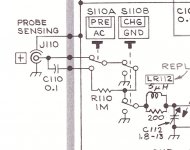
some PAR/EG&G lock-in amplifiers have input ac/dc/gnd selector configured that way, that in gnd position input cap is charged from the signal source, but the input is shorted to gnd (this requires 0 dc on the input gate). I also noticed gate leakage with 100M resistor.I reduce the input bias resistor from 110 Meg to 4.7 Meg
I will sumarise what I think you have been telling me is the set up procedure.
please tell me if any part is wrong.
Apply 12Vdc to power.
adjust VR2 to give an output offset of ~ 6Vdc (half supply voltage)
Check the current through R3. This is jFET Id.
What is the target Id? when the output reaches half supply voltage?
I found that Ir9 is over 8mA. Most coming through R10 from the output !
some PAR/EG&G lock-in amplifiers have input ac/dc/gnd selector configured that way, that in gnd position input cap is charged from the signal source, but the input is shorted to gnd (this requires 0 dc on the input gate). I also noticed gate leakage with 100M resistor.
I believe that the Tektronix 7a22n and 5a22n differential preamplifiers do so similarly. On the 5A22N, there is a "precharge" button, don't have a 7A22N anymore.
The manual is available on BAMA: http://bama.edebris.com/download/tek/7a22/7a22-differential-amplifier-plug-in.pdf
Discussion of gate current compensation.
But my 25 BF862 seem to have some leakage, the 110 Meg
sometimes drop 1.5V DC from the bias servo.
I made one of these circuits on RS proto-board and the leakage was very evident.
Time for dead-bug and through-hole components, or those little teflon standoffs.
I made one of these circuits on RS proto-board and the leakage was very evident.
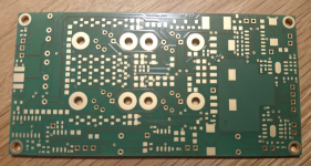
I cannot get replenishment of this plated-through power plane board which used
to be made by Vero. The stuff I can get is not plated-through, so the square pads
on the other side soon fall off and there is no tin under the solder mask which
makes ground connections harder. And the copper surface corrodes.
Is Vero still around, perhaps with a new name?
Good-quality alternatives are also welcome.
regards, Gerhard
Attachments
I cannot get replenishment of this plated-through power plane board which used
to be made by Vero.
Here's a link to the company's UK website -- they only have one distributor in the US:
Veroboard | The Original Stripboard | Vero Technologies Ltd
The through-plated Vectorboards are expensive:
4610-3 Vector Electronics | Prototyping Products | DigiKey
8024 Vector Electronics | Prototyping Products | DigiKey
Might as well just create your own Gerber files and have them made to your specification.
Gerhard -- your work, as always, is marvelous to look at.
Might as well just create your own Gerber files and have them made to your specification.
Gerhard -- your work, as always, is marvelous to look at.
Thanks, it looks like 106P180-4 V1116-ND fits the bill although I cannot decide
if it has the solder mask.
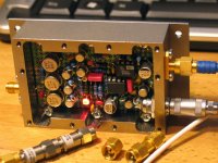
Arghh, everybody can see that I used pliers to attach the Lemo

I agree with Jack.
Just get your own design made by creating Gerber.
Not worth the effort. The previous one lasted 10 years, need only small snippets normally.
But I just got V3 of my BF862 / IF3602 preamp board
")
Attachments
- Home
- Design & Build
- Equipment & Tools
- My version of the G = 1000 low noise measurement amp (for Ikoflexer)