Hello Meanman, i am at SMPS forum once again
I am sorry...this is Rudi thread....i was thinking was Blame ST thread....so, do not mind if my message does not make too much sense..this was to Rudi answer..sorry.
Well Goldkenn..... now a days it is a little bit difficult to have boards.... we have Rudi producing nice board having supply included...you can order in the group buy..and he is producing MKII i think...also you can give a try to the adress i will post you below...maybe Mitchel can have personnal boards for sale....not sure.....because he is busy to build his own boards...he may prefer to sell and to order more in the future....i do not know exactly.
I am also negotiating with the Home forum to produce some boards there (Zharmo lovely boards..asking actually permission to him).... they will be inside group buy too...same philosophy of group buy we have here...low price, cost price.
Also i am sending files to forum management....but this will take a lot of time to produce results...maybe forum, this forum, will produce boards too...they already have some files to use.
I have some boards but i have no way to receive international payment, i have no paypall.... and these boards are just 2 blue boards sets and 2 green boards sets.... i bougth then from group buys in brasil...to my own use and i feel pity to sell them too.
For a while, the best option is to run to Rudi..soon he will have new boards for MKII including beautifull high speed supply on them.
I am very sorry, i would love to help you..but this is all i can do for a while.
Mitchel personal adress....give a try..we never know:
miguelnabuco@terra.com.br
regards,
Carlos
Last edited:
DX Blame MKII - Round 3
Dear DX Blame friends,
I have been busy in the past days upgrading the audio-equipment in my workroom with a pair of Behringer 2031P speakers.
The 2031P speakers have been offered in a special sale with a price of 125€ here in Germany.
They play very well with my DX BlameES prototpye, and I spent several hours in my workroom last night, listening to the beautiful sound,
that the DX Blame and the Behringers have been producing.
Regarding my next contribution to the famous DX Blame family:
The layout of my DX Blame MKII version is done.
A friend of mine, MeTal, is doing some cosmetic revisions right now, I have to check once more the components' names and values,
the polarity of the electrolyts, the pinouts of the transistors, ...
But this is, what I will offer you, and you can sign in the 3rd round right now.
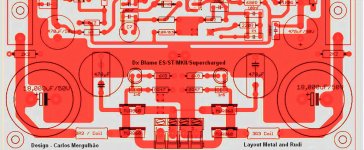
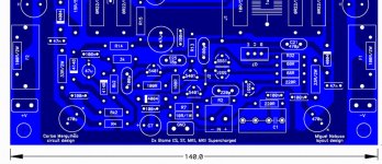
My DX Blame MKII will support the DX Blame ST, the DX Blame ES, the DX Blame MKII and the DX Blame Supercharged model
and thus has the same flexibility as Miguel Nabucco's blue PCBs have.
In contrast to Miguel's design, my DX Blame MKII PCB includes the PSU on-board additionally.
I always felt, that my DX BlameES prototype, that uses the same onboard-PSU feature, plays quicker and
with more dynamics, than Volker's DX BlameES does, using the same components, but set up traditionally, with separate AMP and PSU PCBs.
The current size of the PCB (intended for use with an ALU - L - profile to mount the transistors) is 145 x 150 mm.
Since there are only 2 wires, that have to be soldered manually, I will go for a single-sided PCB.
As the colour of the soldermask, you can decide between: green, blue, red, black, yellow and white.
You can also decide, whether you want to mount the transistors horizontally, on the ALU - L - profile, or vertically.
The price per PCB will be about 12€ (excl. shipping), if the amount of PCBs ordered is > 20 pcs.
Feel free and sign in and tell me, how the PCBs shall look like.
Best regards - Rudi_Ratlos
Dear DX Blame friends,
I have been busy in the past days upgrading the audio-equipment in my workroom with a pair of Behringer 2031P speakers.
An externally hosted image should be here but it was not working when we last tested it.
The 2031P speakers have been offered in a special sale with a price of 125€ here in Germany.
They play very well with my DX BlameES prototpye, and I spent several hours in my workroom last night, listening to the beautiful sound,
that the DX Blame and the Behringers have been producing.
Regarding my next contribution to the famous DX Blame family:
The layout of my DX Blame MKII version is done.
An externally hosted image should be here but it was not working when we last tested it.
A friend of mine, MeTal, is doing some cosmetic revisions right now, I have to check once more the components' names and values,
the polarity of the electrolyts, the pinouts of the transistors, ...
But this is, what I will offer you, and you can sign in the 3rd round right now.
My DX Blame MKII will support the DX Blame ST, the DX Blame ES, the DX Blame MKII and the DX Blame Supercharged model
and thus has the same flexibility as Miguel Nabucco's blue PCBs have.
In contrast to Miguel's design, my DX Blame MKII PCB includes the PSU on-board additionally.
I always felt, that my DX BlameES prototype, that uses the same onboard-PSU feature, plays quicker and
with more dynamics, than Volker's DX BlameES does, using the same components, but set up traditionally, with separate AMP and PSU PCBs.
The current size of the PCB (intended for use with an ALU - L - profile to mount the transistors) is 145 x 150 mm.
Since there are only 2 wires, that have to be soldered manually, I will go for a single-sided PCB.
As the colour of the soldermask, you can decide between: green, blue, red, black, yellow and white.
You can also decide, whether you want to mount the transistors horizontally, on the ALU - L - profile, or vertically.
The price per PCB will be about 12€ (excl. shipping), if the amount of PCBs ordered is > 20 pcs.
Feel free and sign in and tell me, how the PCBs shall look like.
Best regards - Rudi_Ratlos
I do think the board is nice...very well made
I suggest you to post your name and Metal as layout designer... of course if you want...this is your right...you have made it.
What colour they will be?.... red and gold?.... blue and white or other colour?
I hope you keep your tradition with the lovely red and gold boards..but this is not that important to me...what matters is to provide boards for the community.
Thank you, very good work.
regards,
Carlos
Attachments
Last edited:
Hi Rudi,
The Board design looks great to me(thanks for your hard work and Metals for designing it, and obviously thanks to Uncle Charlie for making it available to us all) I really dont mind what colour it ends up...only the sound is important to me")
Please put me down for 4 boards...I will be making 2 dual mono amps
1 for my brother and 1 for me. Do you think you will still do the Parts Kit? As i would also like to get those.
Another question...do you/or will you be selling the speaker protection boards as well? if yes how many would i need?
Thanks for your help in advance.
Alon
The Board design looks great to me(thanks for your hard work and Metals for designing it, and obviously thanks to Uncle Charlie for making it available to us all) I really dont mind what colour it ends up...only the sound is important to me
Please put me down for 4 boards...I will be making 2 dual mono amps
1 for my brother and 1 for me. Do you think you will still do the Parts Kit? As i would also like to get those.
Another question...do you/or will you be selling the speaker protection boards as well? if yes how many would i need?
Thanks for your help in advance.
Alon
Hi, Rudi.
Thanks to you and MeTal for your work in producing these new boards.
Please put me down for 4 boards and my preference would be your trademarked red and gold but I leave the final call to you, as with Alon, performance is the key.
I noticed the value of the caps in the power rails at 18000uf. That value in audio grade is hard to come by around here (DigiKey, Future Elec don't stock them). Will performance be noticeably affected by using lower value or GP grade caps??
As I missed the last round, I have no copy of your much talked about manual, will these new boards come with a copy of the manual ???
Thanks again,
JPR
Alon,
I can of course offer the LS Protect PCBs as well.
One PCB is needed per speaker.
If you like to have, I can also offer you a proven "Soft-Power On" PCB in this round.
When I am talking about a "Small component kit", I am thinking of:
- Input cap C1 (4.7µF resp. 1 µF)
- MICA caps (depending on model built)
- Power caps
- Trim resistor 500R
- VAS MJE - transistors and BD139
- Mur860 rectifier diodes
- Power transistors
- Emitter resistors
Maybe somebody of you knows a good source for reasonably priced components and lets us participate
or somebody knows a reliable source, from where I can order NJW0 / MJW0 - OnSemi Output transistors (for example).
Best regards - Rudi_Ratlos
Hi Rudi,
Then i would like to also get 4 LS protect pcb's And soft start Pcbs.
I have not decided what model to build yet...but will probably just go for MkII Supercharged..not sure i need all that power though..but may as well build the best. I will be using it with these speakers..The Wd25t Ex
Designing Loudspeakers - WD25T EX - The next step
I will try and use it with my current preamp which is a Lightspeed combined with DCB1 Hotrod...but i might be thinking about trying the preamp that you mention, but this wont be till much later.
And if there are enough people interested, i would definitely go for the Small Kit parts for 4 boards.
Thanks Again Rudi
Alon.
Hi Rudi,
I end up decide to order 10pcs, 5 or 6 mono block for my AV system, 4 maybe a trail of full balance mono block, so please resever 10pcs for me.
I refer red and gold as your previous version.
By the way, confirm me once you receive the postage.
P.S. Since I am not log-in fequently, plus I may need to travel a lot for business trip, so please contact me via email, I will email you my email, thanks.
I have been asked, where and how to connect the speakers' wires.
Have a look into the Builder's Manual, page 26, please:
Connect the AMP's speaker's output to either the relay input of the LSProt PCB (in case you have bought it as well)
or directly to the speaker's input connector.
In case you have also bought the PSU PCB, connect a speaker's return wire to a connector, marked with a green "star"
(this is the "Starground area") on the PSU's PCB (see the image above, the blue wire).
In case you did not order my PSU PCB, do it the same with your own PSU.
If you have 2 PSU PCBs (Dual-monoblock design), each channel has its own PSU and starground, that does not interfere with the other one.
If you drive the AMP's 2 channels from one PSU, make sure to connect both speaker's return wires to the PSU's starground.
In case you have a metal case (I do not have) and want an ellectrically required and proven Protect Earth connection as well:
drill a hole into the bottom plate of your case and run a thick wire(s) from a starground-connector to this hole and bolt it together with the PE wire.
Best regards - Rudi_Ratlos
Have a look into the Builder's Manual, page 26, please:
An externally hosted image should be here but it was not working when we last tested it.
Connect the AMP's speaker's output to either the relay input of the LSProt PCB (in case you have bought it as well)
or directly to the speaker's input connector.
In case you have also bought the PSU PCB, connect a speaker's return wire to a connector, marked with a green "star"
(this is the "Starground area") on the PSU's PCB (see the image above, the blue wire).
In case you did not order my PSU PCB, do it the same with your own PSU.
If you have 2 PSU PCBs (Dual-monoblock design), each channel has its own PSU and starground, that does not interfere with the other one.
If you drive the AMP's 2 channels from one PSU, make sure to connect both speaker's return wires to the PSU's starground.
In case you have a metal case (I do not have) and want an ellectrically required and proven Protect Earth connection as well:
drill a hole into the bottom plate of your case and run a thick wire(s) from a starground-connector to this hole and bolt it together with the PE wire.
Best regards - Rudi_Ratlos
Last edited:
Dear DX Blame friends,
those of you, who are going to build the SuperCharged version of the DX Blame and will equip it with one or two transformers rated at > 500 (!) Watts totally,
may also want to have a "Soft-Power-On" circuit, that prevents the fuses to be blown due to the high inrush current, that flows,
when you turn you big transformers on.
Here is what you need.
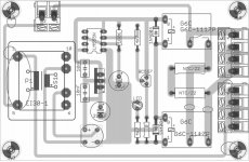
Connect the "hot" wire of your 115VAC resp. 220 VAC mains voltage to Pin 4 of connector X1 and the return wire of the mains to Pin 1 of connector X2.
Connect your transformers to Pins 1-3 of connector X1 resp. Pins 2-4 of connector X2.
The hot wire is connected to connector X3 as well. Insert a switch between the 2 poles of connector X3.
This switch can be a very small, nice-looking one, being capable to switch 220V/250 mA.
This is the switch to turn your AMP on.
The onboard-transformer is a EI30 type, 12 VAC/250mA.
Its output is regulated by a 7812 voltage regulator.
As soon as the 7812 shows 12 VDC at its output, relay K1 (Omron G6C-117P) switches on, and the current is flowing through 2 thermistors
with a total resistance of 44 Ohms, thus delimiting the inrush current to the transformers to about 5A.
(In case you are operating from a 115VAC mains voltage, take 2 thermistors of 10 Ohms each).
The 7812 voltage regulator also provides the voltage for a LM555 timer, that triggers its output at pin 3, as soon as the delay,
defined by R1/C1, has passed.
Then relay K2 will be switched on as well, bypassing the thermistors, and the current can flow without any limitation.
I used 100K/10µF as R1/C1, giving a delay time of about 1 sec.
This time is big enough for the transformers to get "settled", and you do no more be afraid, that any fuse in your house will be blown.
I am using this circuit since several months.
I append the PDF - solder side of the circuit to this post, so you can either etch it yourself or ask an etching company in your country,
if you want to have a "Soft-Power-On-Delay" - PCB.
Best regards - Rudi_Ratlos
those of you, who are going to build the SuperCharged version of the DX Blame and will equip it with one or two transformers rated at > 500 (!) Watts totally,
may also want to have a "Soft-Power-On" circuit, that prevents the fuses to be blown due to the high inrush current, that flows,
when you turn you big transformers on.
Here is what you need.
An externally hosted image should be here but it was not working when we last tested it.
An externally hosted image should be here but it was not working when we last tested it.
Connect the "hot" wire of your 115VAC resp. 220 VAC mains voltage to Pin 4 of connector X1 and the return wire of the mains to Pin 1 of connector X2.
Connect your transformers to Pins 1-3 of connector X1 resp. Pins 2-4 of connector X2.
The hot wire is connected to connector X3 as well. Insert a switch between the 2 poles of connector X3.
This switch can be a very small, nice-looking one, being capable to switch 220V/250 mA.
This is the switch to turn your AMP on.
The onboard-transformer is a EI30 type, 12 VAC/250mA.
Its output is regulated by a 7812 voltage regulator.
As soon as the 7812 shows 12 VDC at its output, relay K1 (Omron G6C-117P) switches on, and the current is flowing through 2 thermistors
with a total resistance of 44 Ohms, thus delimiting the inrush current to the transformers to about 5A.
(In case you are operating from a 115VAC mains voltage, take 2 thermistors of 10 Ohms each).
The 7812 voltage regulator also provides the voltage for a LM555 timer, that triggers its output at pin 3, as soon as the delay,
defined by R1/C1, has passed.
Then relay K2 will be switched on as well, bypassing the thermistors, and the current can flow without any limitation.
I used 100K/10µF as R1/C1, giving a delay time of about 1 sec.
This time is big enough for the transformers to get "settled", and you do no more be afraid, that any fuse in your house will be blown.
I am using this circuit since several months.
I append the PDF - solder side of the circuit to this post, so you can either etch it yourself or ask an etching company in your country,
if you want to have a "Soft-Power-On-Delay" - PCB.
Best regards - Rudi_Ratlos
Attachments
The current status:
@HotChocolate (CafeNoir): may I have your votes, please?
Best regards - Rudi_Ratlos
An externally hosted image should be here but it was not working when we last tested it.
@HotChocolate (CafeNoir): may I have your votes, please?
Best regards - Rudi_Ratlos
Rudi, not so bad but I have a couple remarks.
1 Traces to close to the screwholes, > 8 mm
2 Why don't you swap the primary connections for the transformers?
3 Fater traces for the 230 V nets. Do you plan to use 70 or 105 um copper?
4 It's rather unnecessary to feed the relays with stabilized voltage.
5 The BC557 doesn't need a jumper. Move the 4k7 and let this part be jumper.
Attachments
Last edited:
Rudi, two 350 watts transformers or a single one
able to sustain 700 watts will be better.
This amplifier is informed as a 100/200 watts power amplifiers... and this was made this way in combination with the power supply, a 350 watts transformer will be the limiting factor that will protect output power transistors (only two pairs used to save folks money, to be cheap, to be simple).
If people use 500 watts transformer to each channel, (for instance), the amplifier will be able to put out 65 percent of this power...or something around 330 watts in 4 ohms if the listener tolerate a little distortion.
Power transistors will be forced to work into their limits...and people, sometimes, driver their amplifier hard.... this may damage the amplifier if the guy insert a sustained level of square waves, distorted music from heavy metal guitars or other modern sustained music that is already distorted in the master and added to amplifier distortions at high levels will drive the machine too hard.
I have already measured this power...the amplifier really does that... to limit that huge power, and because my bad L shape adaptors i am using a single 550 watts power transformer...but a 700 watts can be used too.
I do suggest people, to be in the safest side, to bougth two 350 watts transformers or a single 700 watts transformer.
Because of modern music, i do believe people tolerate much more distortion that i had in my imagination ten years ago.... this amplifier with moderate distortions can really put out a lot of watts...a loosen speaker wire will have arcs of voltage jumping from the wire to the connector... and this is a litle bit dangerous....my transformer ratio is conservative and made that way on purpose and premeditated to allow us to use only two pairs in the output.
This power amplifier, cannot operate 2 ohms and not even 3 ohms......users must check their speakers...i have tested with some crazy ones here and i felt the amplifier was beeing forced into the limits when the speaker has some dips, or valleys of impedance because of passive crossovers or the speaker itself and have drops of impedance in some frequency.
I do think i may be a good idea to cut off board to allow people to assemble power transistor direct to the heatsink, to avoid thermal resistance to heat transference.
Please folks, substitute both VAS transistors by MJE15032 to 55 volts models and to BD139 to 35 volts models...keep the 220 ohms first VAS emitter resistance and increase 33 ohms rail resistance wattage to 1 watt...install heatsinks in both VAS transistors to the 55 volts model (Supercharged)
Nice circuit Rudi.
regards,
Carlos
Excuse me to butt in but I might arrange a group buy if you guys are interested my softstart.
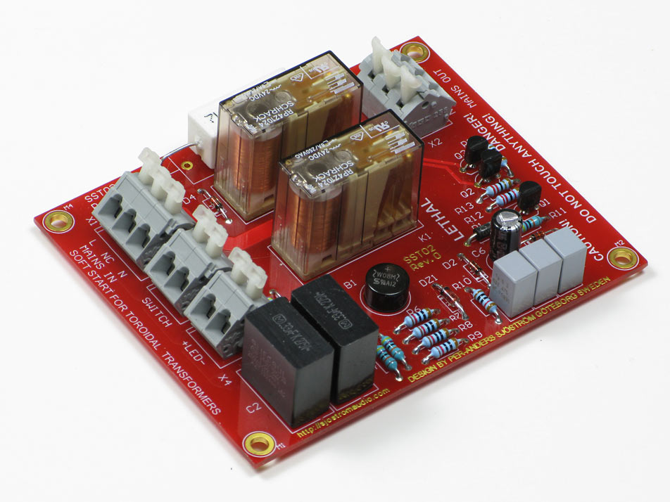
The difference between Rudi's and my design is that I don't use a transformer and the delay can't be so long as with a 555 but 600 ms is sufficient for most applications. My design is also "hot", lethal to touch, always.
The difference between Rudi's and my design is that I don't use a transformer and the delay can't be so long as with a 555 but 600 ms is sufficient for most applications. My design is also "hot", lethal to touch, always.
- Status
- This old topic is closed. If you want to reopen this topic, contact a moderator using the "Report Post" button.
- Home
- Group Buys
- DX Blame Group Buy