Hello,
Is this the amplifier you are doing a group buy for ?
http://audio-circuit.dk/images/LYNX-v3-0-QAG.pdf
Yes...That is the one
sorry guys ...i ve been way to bussy to follow the thread ...please refresh me up
yes i would like four boards ... i dont have pay pal account but i will be more than happy to pay through western union or direct bank deposit .... please email me with total cost of boards +PP+payment method / details
thank you
yes i would like four boards ... i dont have pay pal account but i will be more than happy to pay through western union or direct bank deposit .... please email me with total cost of boards +PP+payment method / details
thank you
Can I suggest an improved wiring arrangement for section9 of the pdf?
The two AC and centre tap be a twisted triplet to the rectifier.
The +ve,-ve and centre tap be a twisted triplet from rectifier to the smoothing capacitor bank.
The Chassis connection can as shown be from the centre of the smoothing caps.
The mains DC supplies +ve, -ve and Power Ground be taken as a twisted triplet to the amplifier Power input end.
Part way along this twisted triplet add a tapping point to the Power Ground.
Use this new point as the Main Audio Ground (Star Ground).
Take the RCA return to Audio Ground.
Take the Signal Ground and signal as a twisted pair to the RCA Hot and to the RCA Return.
Take the Speaker Return and the Signal hot/out as a twisted pair to the Audio Ground. Connect the Signal hot/out to the PCB and keep the Speaker Return continuous on it's route to the Main Audio Ground.
This arrangement removes the charging pulses and all the HF harmonics flowing between transformer and smoothing caps into a separated circuit that cannot adversely influence the circuits connected to the Main Audio Ground. This separation of Audio from Charging is important.
Last edited:
Andrew...It is alway's the best scenario to keep the power supply caps charging currents from the audio signal. To do that I typically use an CRCCC arrangement. The charging peaks on the caps feeding the amplifiers are much slower.
Also a double bridge arrangement allows you to place the star ground at the clean end of the power supply.
Also a double bridge arrangement allows you to place the star ground at the clean end of the power supply.
PR,
I do not see a twisted triplet from transformer to rectifier (your dual secondaries need two twisted pairs from transformer to dual rectifiers), nor from rectifier to smoothing caps, nor from smoothing caps to amp PCB.
I see three connections in the middle of the strap forming the Zero Volts. What are they?
Tara,
CRCCC does not ensure separation of charging currents from audio currents. It's the wire layout that ensures the separation, not the components used.
Last edited:
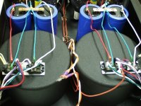
where? Not in the pic you posted. I see single wires between transformer to rectifiers and single wires between rectifiers and smoothing caps and single wires between smoothing caps and next stage.It's what I do !
These single wires create big loop areas. Those big loop areas create interference in all other stages of the amplifier.
for every "circuit" that has a flow and return route then the pair of flow and return must have a low loop area to minimise pick up of interference from other noisy sources and to minimise the radiation of interference from this circuit.
Where the flow and return involve three wires (as in a dual polarity supply to an amplifier), all three wires must be formed into a triplet with low loop area.
Twisted is the easiest way to achieve low loop area and low interference with wiring.
Parallel close space traces on a PCB achieve similar.
Where the flow and return involve three wires (as in a dual polarity supply to an amplifier), all three wires must be formed into a triplet with low loop area.
Twisted is the easiest way to achieve low loop area and low interference with wiring.
Parallel close space traces on a PCB achieve similar.
- Status
- This old topic is closed. If you want to reopen this topic, contact a moderator using the "Report Post" button.
- Home
- Group Buys
- GB: New run Lynx 3.01 amp by Jan Dupont