And for me, does the schematic looks OK?  I didn't shunted the I/V res. when soldered.
Still can't figure what would I do with two different voltage GND from DC ref. board common in the 3.5mm jack for headphone amp.
When I common I get different readings for DC voltage vs. when I measure each channel with it's own GND.
DC reference is used to obtain DC-coupled output by lifting output GND reference voltage to the same DC level as the I/V converter outputs.
When using two monoblocks it is possible to use two separate reference voltages in order to trim DC output to exactly 0V for each channel.
But when driving a headphone with common GND connection or a stereo (pre) amplifier we need a single GND reference.
I suggest to install a single 500 Ohms potentiometer for GND ref.
Connect both decoupling caps in parallel in order to double bypass capacitance. Then trim for lowest and equal DC-offset on both L and R outputs.
So remove both DC reference pots, put in one 470 … 500R pot and connect the decoupling cap of the other channel to the wiper of this pot. Then use the wiper of this pot as single GND reference.
DC offset differences between L and R channels are usualy caused by tolerances in the TDA1541A on-chip current reference sources.
This means we can null L/R channel DC-offset by fine tuning the I/V resistor value. Measure the voltage across both I/V resistors (after completing MOSFET current buffer trimming). Lower the I/V resistor value that has slightly higher voltage across it, so it exactly matches the voltage across the other I/V resistor.
The easiest way to do this is placing a suitable high ohmic resistor in parallel with the I/V resistor that has highest DC voltage across it.
Hello!
Thanks for the great response!
I'm not planning to use a second Red Baron DAC board (at least for now), so can I skip the DC reference PCB and use the common analog GND output and L & R output through capacitors?
If yes, what value to use, and maybe some recommendation? (Ampohm, Mundorf, PIO etc.)
Kind rgs,
Alex.
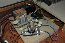
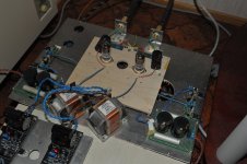
Red baron working !!
Thanks to John and Oliver .
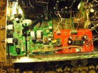
The Red Baron is singing and I hope the wiring for the Dc reference module is OK . I manage to null the dc across the IV resistor.
I post my build and I hope my wiring is correct.
Anyway I have input caps in my pre .
Sounds very relax, 3D imaging. Outstanding high, mid and low .
Vocal is especially detail.
regards
kp93300
Thanks to John and Oliver .
The Red Baron is singing and I hope the wiring for the Dc reference module is OK . I manage to null the dc across the IV resistor.
I post my build and I hope my wiring is correct.
Anyway I have input caps in my pre .
Sounds very relax, 3D imaging. Outstanding high, mid and low .
Vocal is especially detail.
regards
kp93300
Attachments
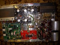
Hi,
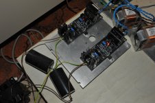
Red Baron is up and running.")
I don't use anymore the reference DC module. I coupled direct the analog exit through 1uF capacitors, and now I have the common ground. Before caps I have ~1VDC.
I feed the signal to an O2 headphone amp that feeds HD600.
Sounds really nice even with those capacitors and crappy I/V resistors.
Now I have to make a nice housing and get some ''snake-oil'' resistors and caps.
Thanks a lot for your great support, and the patience to answer to my questions!
Kind rgs,
Alex.
Red Baron is up and running.
I don't use anymore the reference DC module. I coupled direct the analog exit through 1uF capacitors, and now I have the common ground. Before caps I have ~1VDC.
I feed the signal to an O2 headphone amp that feeds HD600.
Sounds really nice even with those capacitors and crappy I/V resistors.
Now I have to make a nice housing and get some ''snake-oil'' resistors and caps.
Thanks a lot for your great support, and the patience to answer to my questions!
Kind rgs,
Alex.
Attachments
End of Project
P.S.: A few PCB´s from the project are still in stock
Dear diyaudio friends,
after now 7 years, my TDA1541A DAC project comes to the end.
It was a great pleasure to develop this project with much help from the community.
Thank you all, you were GREAT!
My special thanks goes to John -ecdesigns- for his support over the years.
In the next days i will disassemble all parts of my own DAC for sale.
For those who are interested, stay tuned to my blog. You will find the parts with prices shortly.
Audiophlile Greetings
Oliver
P.S.: A few PCB´s from the project are still in stock
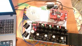
Thank you Oliver for all the work you have put into this project! I still have my Red Baron, I'm still enjoying it every day - and I'm still tweaking it. It looks like a mess but with this D3a output stage it sounds really excellent.
Attachments
Yes, a big thank you to Oliver.
Any future projects in the works?
ATM no, just for myself...
Thank you Oliver for all the work you have put into this project! I still have my Red Baron, I'm still enjoying it every day - and I'm still tweaking it. It looks like a mess but with this D3a output stage it sounds really excellent.
Looks marvelous!

Hi Oliver,
I feel I'm really lucky not being late with Red Baron acquisition. During the Christmas season I managed to assembly it with Ians fifo kit and this composition sounds amazing! Although its only with I2S connection and with simple TDA1541A chip, still having the possibility to improve.
Thank you for the great music player device!
Gábor
I managed to assembly it with Ians fifo kit Gábor
Is there any chance of seeing a pic of your work? I got sort of stuck with my FIFO kit but a pic might just get me going again.
Meanwhile, many, many thanks to Oliver for his work and for his patient support over the years. I bought my first board way back in 2010 (a friend is still using it) and have been using and enjoying TDA1541 DACs ever since. The forum has been a pleasant place to visit over the years.
Best wishes
Dave
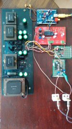
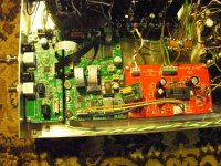
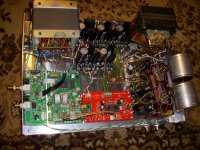
OK guys, lets see how I can upload pictures (first time for me here)
Some comments.
- this is not the final version, kind a breadboard, just to see whether it works or not
- transformers are pulled out from previous projects
- I2S to PCM modul is missing, I'm on the group buy list as you may see
- I2S connection is made with Ian's connector, just the ground wires are extracted exept for 1 piece
- Crystek CCHD 957 45MHz oscillator is installed, 49MHz one is still what I got from Ian - not so important for me
- all B+ are chinese printed boards, populated with CREE SiC diodes and LM317 regulators, Black gate capacitors. Regulator IC-s will be replaced by more sophisticated ones, but I have not decided which ones.
- current/voltage converter resistors are 47 ohm Z foils
- analog section is made with 6072 tubes
- annoying that the spdif board wakes always with optical source as default, a switch needs to be wired to the front to switch to coaxial source which I use
Any question?
Regards, Gábor
Attachments
Great pictures! I'll bet it sounds nice with thouse 6072's. Is it cathode follower Kondo style?
Yes I have a couple of questions: How many boards do one need from Ian if one is going with I2s input, and what are they called? And last but not least, how many powersupplies are needed?
Yes I have a couple of questions: How many boards do one need from Ian if one is going with I2s input, and what are they called? And last but not least, how many powersupplies are needed?
Thanks!
- the analog section is really a Kondo style with an anode follower and a Cathode follower next. The currents are increased a bit because I used lower anode resistor - 62K - and lower cathode resistor - 68k - well, the chance to have 2W Shinkohs is a bit limited and I had these on the self.
- if you go with I2S then you do not need SPDIF board, the widest green one on my picture.
- You need a FIFO board,
- a clock module - you should choose which one, I suggest the dual XO board which I use but please follow Ian's recommendation and replace the generic oscillator with at least a Cristek CCHD 957 xxMHz one. Or if you are a maximalist, you can choose an OCXO instead at a price of 10*.
- all above were the minimum. In this case you will have a reclocked FIFO with a precise I2S input-output.
- you can further improve the system with an Isolator board - I have one but not yet installed. It's not a must, you can live without.
- some states that the best ever is the I2S to PCM board which transforms the I2S signal to the PCM which the dac chip expects directly. Since I was late for the last group buy, I could not buy this board, because Ian had run out of them.
- Ian's power supplies - the actual digital installation needs only one +5V power supply, because the boards supply each other. But if you use an I2S isolator board, you will need one more +5V. I think when I have a PCM board, I will need a plus +5V. You can see a sidebar regulator for 3,3V, which uses the main 5V, this board supply the oscillators. You can use here another +3,3V regulator or a battery. I suggest to start with Ian's TPS7A based board and replace If needed. The Red Baron needs 4 different voltages, as yo can see on the board.
Well, I handed over 2-3 months information gathering I strongly recommend to read through Ian's manual in order not to make mistakes. In Ian's each posts you can find exactly the link to the manuals.
Cheers,
Gábor
- the analog section is really a Kondo style with an anode follower and a Cathode follower next. The currents are increased a bit because I used lower anode resistor - 62K - and lower cathode resistor - 68k - well, the chance to have 2W Shinkohs is a bit limited and I had these on the self.
- if you go with I2S then you do not need SPDIF board, the widest green one on my picture.
- You need a FIFO board,
- a clock module - you should choose which one, I suggest the dual XO board which I use but please follow Ian's recommendation and replace the generic oscillator with at least a Cristek CCHD 957 xxMHz one. Or if you are a maximalist, you can choose an OCXO instead at a price of 10*.
- all above were the minimum. In this case you will have a reclocked FIFO with a precise I2S input-output.
- you can further improve the system with an Isolator board - I have one but not yet installed. It's not a must, you can live without.
- some states that the best ever is the I2S to PCM board which transforms the I2S signal to the PCM which the dac chip expects directly. Since I was late for the last group buy, I could not buy this board, because Ian had run out of them.
- Ian's power supplies - the actual digital installation needs only one +5V power supply, because the boards supply each other. But if you use an I2S isolator board, you will need one more +5V. I think when I have a PCM board, I will need a plus +5V. You can see a sidebar regulator for 3,3V, which uses the main 5V, this board supply the oscillators. You can use here another +3,3V regulator or a battery. I suggest to start with Ian's TPS7A based board and replace If needed. The Red Baron needs 4 different voltages, as yo can see on the board.
Well, I handed over 2-3 months information gathering
I strongly recommend to read through Ian's manual in order not to make mistakes. In Ian's each posts you can find exactly the link to the manuals.Cheers,
Gábor
OK guys, lets see how I can upload pictures (first time for me here)
Some comments.
- this is not the final version, kind a breadboard, just to see whether it works or not
- transformers are pulled out from previous projects
- I2S to PCM modul is missing, I'm on the group buy list as you may see
- I2S connection is made with Ian's connector, just the ground wires are extracted exept for 1 piece
- Crystek CCHD 957 45MHz oscillator is installed, 49MHz one is still what I got from Ian - not so important for me
- all B+ are chinese printed boards, populated with CREE SiC diodes and LM317 regulators, Black gate capacitors. Regulator IC-s will be replaced by more sophisticated ones, but I have not decided which ones.
- current/voltage converter resistors are 47 ohm Z foils
- analog section is made with 6072 tubes
- annoying that the spdif board wakes always with optical source as default, a switch needs to be wired to the front to switch to coaxial source which I use
Any question?
Regards, Gábor
TOP Gábor, thumbs up!
Thanks!
In Ian's each posts you can find exactly the link to the manuals.
I checked last night and saw that it's just over three years ago that I bought the parts from Ian. Oops. It's probably time I got them going.
Your comments and, esp, your pics just might be the encouargement I need. Thanks!
Dave
Thanks!
- the analog section is really a Kondo style with an anode follower and a Cathode follower next. The currents are increased a bit because I used lower anode resistor - 62K - and lower cathode resistor - 68k - well, the chance to have 2W Shinkohs is a bit limited and I had these on the self.
- if you go with I2S then you do not need SPDIF board, the widest green one on my picture.
- You need a FIFO board,
- a clock module - you should choose which one, I suggest the dual XO board which I use but please follow Ian's recommendation and replace the generic oscillator with at least a Cristek CCHD 957 xxMHz one. Or if you are a maximalist, you can choose an OCXO instead at a price of 10*.
- all above were the minimum. In this case you will have a reclocked FIFO with a precise I2S input-output.
- you can further improve the system with an Isolator board - I have one but not yet installed. It's not a must, you can live without.
- some states that the best ever is the I2S to PCM board which transforms the I2S signal to the PCM which the dac chip expects directly. Since I was late for the last group buy, I could not buy this board, because Ian had run out of them.
- Ian's power supplies - the actual digital installation needs only one +5V power supply, because the boards supply each other. But if you use an I2S isolator board, you will need one more +5V. I think when I have a PCM board, I will need a plus +5V. You can see a sidebar regulator for 3,3V, which uses the main 5V, this board supply the oscillators. You can use here another +3,3V regulator or a battery. I suggest to start with Ian's TPS7A based board and replace If needed. The Red Baron needs 4 different voltages, as yo can see on the board.
Well, I handed over 2-3 months information gathering
Cheers,
Gábor
Thank you so much for taking the time. This is just the information I (and probably several others) needed.
I would like to thank Oliver for the Red Baron project and his generous support to the DIY community over the years.
I have been using the Red Baron 5.0 and the Olivers Tube-I-Zator board for a couple of months, and so far I am very impressed with the result.
But my build seems to suffer from some kind of grounding issue. When I play music through my DAC, and I touch the volume control or the enclosure of my TVC preamplifier (Stevens & Billington) there is a hum through the speakers. The problem is only there when I listen to my Red baron DAC.
When I listen to my Salas Folded simplistic RIAA or my old DAC there is no such hum.
It is not a huge problem, as the hum isn't there unless I touch my preamlifier, but I would certainly like to eliminate the problem once and for all.
All help will be greatly appreciated.
- Status
- This old topic is closed. If you want to reopen this topic, contact a moderator using the "Report Post" button.
- Home
- Group Buys
- "Reference" TDA1541A DAC with I2S-BUS architecture