Sure, here are few pics.
DTSES
We never heard if you felt better about it after it settled in a bit. I would think 50 hrs might open it up quite a bit.
Your work is nice and neat. A lot of work has gone into it. As an arm chair quaterback, I wonder if your physical layout is contributing to lack luster sound.
You end up with pretty long runs from shunts to consumers. I have heard people say if you can't get down to a couple inches, really not much value in the shunt.
Also, the I2S runs are pretty long. I wonder if you just re arranged a bit. By rotating the board that feeds the red baron and sliding it into the place of the red baron you could achieve short I2S signals and short power cables from your shunts. Just a thought.
Thanks for advice!
Currently I' working on layout and 4 additional Salas shunts for Ians board and output stage. Also customized toroid with 8 separated windings will be installed. Each line outputs 200mA of current, so I'll set the shunts at 100-120mA each for proper operating conditions. Didn't know about the short wiring here, thanks!
Anyway, the dac is not bad for sure, perhaps just my expectations were quite high due to amount of work and time I spent with it. I think that new additions will bring it to another level. I'll post some pics later.
Last edited:
wlowes
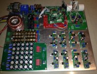
could you please comment on the layout below?
- There are 9 Salas shunts in total, some of them will still have a bit long connection from both sides.
- Ian's PCM board will be placed on top of DAC board
- Will use ipx mini coax cables to connect spdif module to PCM board
- PCM and DAC boards will be hard soldered, 2-3cm cables will go directly to TDA chip.
Attachments
Hi dtses,
You must have ground returns as close as possible to all your I2S lines to the dac or you will have a high impedance on the signal resulting in trigger uncertainty which will give you high amounts of jitter.
I wouldn't be surprised that if you fix this alone the sound quality will improve significantly. Although it must be executed correctly for the best results. Even if you just try twisting a separate ground around each I2S line, it would be better than nothing.
Ryan
wlowes
could you please comment on the layout below?
- There are 9 Salas shunts in total, some of them will still have a bit long connection from both sides.
- Ian's PCM board will be placed on top of DAC board
- Will use ipx mini coax cables to connect spdif module to PCM board
- PCM and DAC boards will be hard soldered, 2-3cm cables will go directly to TDA chip.
Looks much better. Most suggest that the 15V PS to TDA is most critical, so perhaps ensure that this salas shunt has the premium position for short cable.
Hi all,
if anyone was interested in the custom Laptech crystal
http://www.diyaudio.com/forums/grou...hronous-i2s-s-pdif-fifo-kit-group-buy-70.html
please add your name in the wish list at
http://www.diyaudio.com/forums/digital-line-level/203511-any-good-tda1541a-dac-kit-96.html
The minimum orderable quantity from Laptech is 5 pcs for each frequency.
When that quantity will be reached I ask Laptech for a quote.
Andrea
Greetings from Norway.
I have just "finished" my Reference TDA1541A DAC and the music sounds - and more importantly - feels just great. It has rediscovered the soul in my music collection.
Thank you Oliver Mai for making this possible for diy'ers all over the world.
Kind regards,
Vidar
Anyone interested can take a look at the last pictures in this thread:
Red Baron 1541A-I2S-En begynnelse
Greetings from Norway.
I have just "finished" my Reference TDA1541A DAC and the music sounds - and more importantly - feels just great. It has rediscovered the soul in my music collection.
Thank you Oliver Mai for making this possible for diy'ers all over the world.
Kind regards,
Vidar
Anyone interested can take a look at the last pictures in this thread:
Red Baron 1541A-I2S-En begynnelse
Hi Vidar,
great build!

Have much fun and thank´s for your kind words.
Cheers,
Oliver
It's well deserved. I have some experience with the ESS Sabre 9018 DAC and the mid-range, physicality and musicality from the TDA 1541A is in a whole different league. It's so much better on classical and jazz (90% of my music collection) that it isn't even funny (or rather very funny). No more Sigma Delta and oversampling for me.
red baron pcb setup cant seem to find a couple of answers regarding the setup of the red baron PCB, i am going to use the onboard buffer so i have the little DC reference module ready as well, i am ready to power the dac board but there are some adjustments that i am not sure about regarding the 2 output 250k multi trims and the ref mod how to conect and test instructions, can someone point to the instructions thanks
Last edited:


Hi Guys,
I have the waveio isolated i2s connected as per Oliver's suggestions further back in this thread. Is it possible to take the 3.3v required for the waveio isolated i2s on the v+ and isolated ground from the 3.3v salas reg feeding the Red Baron v5 board. I'm not using a FIFO setup and just want to get it working. What is your recommendation for the 3.3v on the waveio isolated i2s?
Thanks for your help.
Hi Guys,
I have the waveio isolated i2s connected as per Oliver's suggestions further back in this thread. Is it possible to take the 3.3v required for the waveio isolated i2s on the v+ and isolated ground from the 3.3v salas reg feeding the Red Baron v5 board. I'm not using a FIFO setup and just want to get it working. What is your recommendation for the 3.3v on the waveio isolated i2s?
Thanks for your help.
You have a PM
")
You could also use the simple version and power the isolated side of the WaveIO from the 3.3V Red Baron side.
Last edited:
confuseion connecting cd pro 2 12 s out to reg baron in?
Hi Ya gents,
sort of a newbee question here!.Sorry to bother but i am sorta stuck.
On my CDPro 2 I can locate the 12 s output connector- a 6pin effort- so i made a colour coded lead to fit-- with the mechanism on the floor and as i look at it square on from left to right , according to the Phillips data sheet :
Pin 1= Misc (N/c on my lead)
Pin 2 = SCLK (Black on my lead)
Pin 3= WCLK (Brown on my lead)
Pin4= DATA (Red on my lead)
Pin5= Gnd ( Orange on my lead)
Pin6= graphics o/p (N/c on my lead)
Now looking at the Red Baron DAC input: 12S Ground is self explanatory
DATA is also self expansionary
However Sclock (from the CD Pro2) is that BCK or FS on the Red Baron I/P?
Also FS, (from the CD Pro2) is that BCK or FS on the Red Baron I/P?
Any help accepted, as i have yet to hear music from the Red Baron (but i know its in there somewhere!)
Thanks Gents
Johnny
Hi Ya gents,
sort of a newbee question here!.Sorry to bother but i am sorta stuck
.On my CDPro 2 I can locate the 12 s output connector- a 6pin effort- so i made a colour coded lead to fit-- with the mechanism on the floor and as i look at it square on from left to right , according to the Phillips data sheet :
Pin 1= Misc (N/c on my lead)
Pin 2 = SCLK (Black on my lead)
Pin 3= WCLK (Brown on my lead)
Pin4= DATA (Red on my lead)
Pin5= Gnd ( Orange on my lead)
Pin6= graphics o/p (N/c on my lead)
Now looking at the Red Baron DAC input: 12S Ground is self explanatory
DATA is also self expansionary
However Sclock (from the CD Pro2) is that BCK or FS on the Red Baron I/P?
Also FS, (from the CD Pro2) is that BCK or FS on the Red Baron I/P?
Any help accepted, as i have yet to hear music from the Red Baron (but i know its in there somewhere!)
Thanks Gents
Johnny
- Status
- This old topic is closed. If you want to reopen this topic, contact a moderator using the "Report Post" button.
- Home
- Group Buys
- "Reference" TDA1541A DAC with I2S-BUS architecture