In general you are better off without buffers, as these increase jitter (hence tailoring the attennuatora to the i2s signal levels will be better).
However, increased jitter on the DATA and WS lines should have only a small effect. Jitter on the BCK line has a large effect. In general some local reclocking scheme for bck should be employed to minimize jitter, rather than taking (inherently more jittery) bck from you transport.
However, increased jitter on the DATA and WS lines should have only a small effect. Jitter on the BCK line has a large effect. In general some local reclocking scheme for bck should be employed to minimize jitter, rather than taking (inherently more jittery) bck from you transport.
Hello TDA1541 lovers. I am a complete newbie when it comes to NOS and R2R dacs, so here are my questions regarding The Red Baron modules.
1) Can this Red Baron TDA1541 implementation accept DSD signal through I2S? Maybe with help of DoP (DSD over PCM)? If not then what is the maximum sampling frequency?
2) What are advantages of stacking two DAC modules? Better SNR? Balanced mode operation? Dual mono operation? Does two modules bring a higher level SQ?
3) Can you tell the difference in SQ between TDA1541 regular, S1 and S2 with all other components untouched?
4) I see the on-board MOSFET I/V stage is very good and simple design, but is it the best sounding one in comparison to other solid state FET I/V stages (not interested in tubes)?
5) Did somebody auditioned a similarly well designed PCM1704 implementation in comparison with this TDA1541? And if yes then what design won in SQ department?
6) Question for dvb-projekt: did you considered PCM1704 when you started your Reference DAC adventure? Why PCM1704 doesn't have as much attention as TDA1541A? On paper PCM1704 looks awesome.
P.S. In advance Pardon me for silly questions. Feel free to correct my mistakes.
Hi TiEx,
to your questions:
The Red Baron is a NOS TDA1541A DAC, witch accepts only 16-Bit. AFAIK the DoP needs 24bit, so no.
The max. sampling frequency i used without any problems is 96kHz over my Teralink X2 USB/I2S converter.
With the Red Baron you could only parallel the TDA1541A.
The current outputs are looped together in a master slave configuration. Paralleling two DAC´s doubles the current output,
increases the THD+N ratio and reduces linearity errors. This gives more dynamic and details.
TDA1541A selections have been made with respect to the maximum differential linearity error. You could read the differences HERE.
I could only tell you the result from my standard TDA1541A to my actual S1 double crown. To make it short, better 3D soundstage, more micro informations .
-ecdesigns- MK7 onboard I/V stage sounds really awesome, but i did´t compare it with all other possible I/V stages.
That´s a question to the community.
Before i start my DAC project i read a lot of reviews and posts through the i-net about the best sounding DAC. My personal choice goes to the TDA1541A.
BTW, the most important thing for me is the sound. You could compare the data sheets, but do you listen to them...")
Best regards,
Oliver
to your questions:
1) Can this Red Baron TDA1541 implementation accept DSD signal through I2S? Maybe with help of DoP (DSD over PCM)? If not then what is the maximum sampling frequency?
The Red Baron is a NOS TDA1541A DAC, witch accepts only 16-Bit. AFAIK the DoP needs 24bit, so no.
The max. sampling frequency i used without any problems is 96kHz over my Teralink X2 USB/I2S converter.
2) What are advantages of stacking two DAC modules? Better SNR? Balanced mode operation? Dual mono operation? Does two modules bring a higher level SQ?
With the Red Baron you could only parallel the TDA1541A.
The current outputs are looped together in a master slave configuration. Paralleling two DAC´s doubles the current output,
increases the THD+N ratio and reduces linearity errors. This gives more dynamic and details.
3) Can you tell the difference in SQ between TDA1541 regular, S1 and S2 with all other components untouched?
TDA1541A selections have been made with respect to the maximum differential linearity error. You could read the differences HERE.
I could only tell you the result from my standard TDA1541A to my actual S1 double crown. To make it short, better 3D soundstage, more micro informations .
4) I see the on-board MOSFET I/V stage is very good and simple design, but is it the best sounding one in comparison to other solid state FET I/V stages (not interested in tubes)?
-ecdesigns- MK7 onboard I/V stage sounds really awesome, but i did´t compare it with all other possible I/V stages.
5) Did somebody auditioned a similarly well designed PCM1704 implementation in comparison with this TDA1541? And if yes then what design won in SQ department?
That´s a question to the community.
6) Question for dvb-projekt: did you considered PCM1704 when you started your Reference DAC adventure? Why PCM1704 doesn't have as much attention as TDA1541A? On paper PCM1704 looks awesome.
Before i start my DAC project i read a lot of reviews and posts through the i-net about the best sounding DAC. My personal choice goes to the TDA1541A.
BTW, the most important thing for me is the sound. You could compare the data sheets, but do you listen to them...
Best regards,
Oliver
Thanks for the answers Oliver. And here a re some more questions about Red Baron.
1) About using your DAC with Ian's Asynchronous I2S FIFO project, an ultimate weapon to fight the jitter http://www.diyaudio.com/forums/digi...ifo-project-ultimate-weapon-fight-jitter.html and with Drive NOS AD1865/62,PCM1704/02/63,TDA1541 from FIFO: Universal I2S-PCM driver board http://www.diyaudio.com/forums/digi...1541-fifo-universal-i2s-pcm-driver-board.html
Here is the info that I have in mind: buffers between the i2s source and TDA1541 i2s input may introduce some jitter no matter how fast they are. TDA1541 is prone to jitter according to a wide variety of DIY people opinions. So wouldn't it be better to adjust i2s attenuators on Red Baron board to the Ian's FIFO source? Ian's FIFO is 3.3V LVTTL logic output level with 5V TTL tolerance, what changes to i2s attenuator on PCB it would require?
2) Second question is about what is better for TDA1541 clean i2s or PCM? I've read somewhere here on diyaudio that TDA1541 gives better SQ when fed by PCM signal. Maybe there is a reason to use Ian's NOS i2s to PCM daughter board? But then again i2s is a Philips invention so wouldn't it be better to feed TDA1541 just with clean i2s signal?
Here is a quote from other thread:
And if using Ian's i2s to PCM converter then how to connect it with Red Baron and what would be the changes to i2s attenuator?
Best regards.
Alex
1) About using your DAC with Ian's Asynchronous I2S FIFO project, an ultimate weapon to fight the jitter http://www.diyaudio.com/forums/digi...ifo-project-ultimate-weapon-fight-jitter.html and with Drive NOS AD1865/62,PCM1704/02/63,TDA1541 from FIFO: Universal I2S-PCM driver board http://www.diyaudio.com/forums/digi...1541-fifo-universal-i2s-pcm-driver-board.html
Here is the info that I have in mind: buffers between the i2s source and TDA1541 i2s input may introduce some jitter no matter how fast they are. TDA1541 is prone to jitter according to a wide variety of DIY people opinions. So wouldn't it be better to adjust i2s attenuators on Red Baron board to the Ian's FIFO source? Ian's FIFO is 3.3V LVTTL logic output level with 5V TTL tolerance, what changes to i2s attenuator on PCB it would require?
2) Second question is about what is better for TDA1541 clean i2s or PCM? I've read somewhere here on diyaudio that TDA1541 gives better SQ when fed by PCM signal. Maybe there is a reason to use Ian's NOS i2s to PCM daughter board? But then again i2s is a Philips invention so wouldn't it be better to feed TDA1541 just with clean i2s signal?
Here is a quote from other thread:
So maybe there is a reason to use i2s to PCM converter?This board Ian is making will allow the option of a simultaneous output of offset binary Left and Right Data. For TDA1541 enthusiasts, and tinkerers, this will allow a person to create a dual mono TDA1541 board. Also possible is a dual differential, or balanced output TDA1541 board.
I know many people will be interested in these possibilities.
And it may be worth nothing, but I have read reports from those that have tried it, that the offset binary data input sounds better than the i2s.
I don't know, but I am keen to try it.
It will also allow the use of the TDA1540 chip.
And if using Ian's i2s to PCM converter then how to connect it with Red Baron and what would be the changes to i2s attenuator?
Best regards.
Alex
Thanks for the answers Oliver. And here a re some more questions about Red Baron.
1) About using your DAC with Ian's Asynchronous I2S FIFO project, an ultimate weapon to fight the jitter http://www.diyaudio.com/forums/digi...ifo-project-ultimate-weapon-fight-jitter.html and with Drive NOS AD1865/62,PCM1704/02/63,TDA1541 from FIFO: Universal I2S-PCM driver board http://www.diyaudio.com/forums/digi...1541-fifo-universal-i2s-pcm-driver-board.html
Here is the info that I have in mind: buffers between the i2s source and TDA1541 i2s input may introduce some jitter no matter how fast they are. TDA1541 is prone to jitter according to a wide variety of DIY people opinions. So wouldn't it be better to adjust i2s attenuators on Red Baron board to the Ian's FIFO source? Ian's FIFO is 3.3V LVTTL logic output level with 5V TTL tolerance, what changes to i2s attenuator on PCB it would require?
2) Second question is about what is better for TDA1541 clean i2s or PCM? I've read somewhere here on diyaudio that TDA1541 gives better SQ when fed by PCM signal. Maybe there is a reason to use Ian's NOS i2s to PCM daughter board? But then again i2s is a Philips invention so wouldn't it be better to feed TDA1541 just with clean i2s signal?
Here is a quote from other thread:
So maybe there is a reason to use i2s to PCM converter?
And if using Ian's i2s to PCM converter then how to connect it with Red Baron and what would be the changes to i2s attenuator?
Best regards.
Alex
Hi Alex,
in the next weeks Chris (crobbins5421) will test different things with the Red Baron and Ian´s FIFO. I think his results will answers also your questions.

Oliver
Awesome news Oliver. Would love to see his results.
Hi Alex,
in the next weeks Chris (crobbins5421) will test different things with the Red Baron and Ian´s FIFO. I think his results will answers also your questions.
Oliver
Hello everyone. There is a question. Is there a kit with ALL parts(no only pcb) to build this DAC ?
P.S. Thanks in advance.
Hi selic2006,
no. This GB is only for the PCB´s.
Best regards,
Oliver
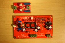
Bargain Sale
Here you could order my ready build Red Baron DAC test module with
-ecdesigns- MK7 onboard I/V stage:
Main Parts
- TX2575 0,1% I/V resistors ($18.80/pair solo)
- PRP resistors
- Sanyo OS-CON SEPC capacitors
and the needed DC Reference module:
Main Parts
- Vishay Bulk Metal Foil 1280G trimmers ($30.70/pair solo)
- Sanyo OS-CON SEPC capacitors
for the special price of
Complete $99
including
Worldwide shipping and paypal fee
If you are interested, please send me a PM.
Bargain Sale
Here you could order my ready build Red Baron DAC test module with
-ecdesigns- MK7 onboard I/V stage:
Main Parts
- TX2575 0,1% I/V resistors ($18.80/pair solo)
- PRP resistors
- Sanyo OS-CON SEPC capacitors
and the needed DC Reference module:
Main Parts
- Vishay Bulk Metal Foil 1280G trimmers ($30.70/pair solo)
- Sanyo OS-CON SEPC capacitors
for the special price of
Complete $99
including
Worldwide shipping and paypal fee
An externally hosted image should be here but it was not working when we last tested it.
An externally hosted image should be here but it was not working when we last tested it.
An externally hosted image should be here but it was not working when we last tested it.
If you are interested, please send me a PM.
Attachments
Bargain Sale
Here you could order my ready build Red Baron DAC test module with
-ecdesigns- MK7 onboard I/V stage:
Main Parts
- TX2575 0,1% I/V resistors ($18.80/pair solo)
- PRP resistors
- Sanyo OS-CON SEPC capacitors
and the needed DC Reference module:
Main Parts
- Vishay Bulk Metal Foil 1280G trimmers ($30.70/pair solo)
- Sanyo OS-CON SEPC capacitors
for the special price of
Complete $99
including
Worldwide shipping and paypal fee
An externally hosted image should be here but it was not working when we last tested it.
An externally hosted image should be here but it was not working when we last tested it.
An externally hosted image should be here but it was not working when we last tested it.
If you are interested, please send me a PM.
Sold!
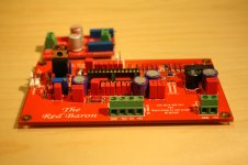
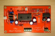
Hi all,
wanted to share a finished Red Baron I am planning to use in an old philips cd player, but unfortunately one of the five 100R capacitors in the mail today was 27.4 k... so I can say it's almost assembled I will have to make a trip to a local electronics shop before connecting and powering up the board.
Oliver: I've noticed the 106C inductor is on some posts oriented one or the other way. In post #766 top picture it's how I have it, on the same post two pictures below it's rotated. Is the 106C sticker sometimes rotated? Plus end is pointing towards +5V and ground is up, right?
Can't wait to finally hear it. I hope it sounds as good as it looks
Thanks,
Martin
wanted to share a finished Red Baron I am planning to use in an old philips cd player, but unfortunately one of the five 100R capacitors in the mail today was 27.4 k... so I can say it's almost assembled
I will have to make a trip to a local electronics shop before connecting and powering up the board.Oliver: I've noticed the 106C inductor is on some posts oriented one or the other way. In post #766 top picture it's how I have it, on the same post two pictures below it's rotated. Is the 106C sticker sometimes rotated? Plus end is pointing towards +5V and ground is up, right?
Can't wait to finally hear it. I hope it sounds as good as it looks
Thanks,
Martin
Attachments
Last edited:
Hi all,
wanted to share a finished Red Baron I am planning to use in an old philips cd player, but unfortunately one of the five 100R capacitors in the mail today was 27.4 k... so I can say it's almost assembled
Oliver: I've noticed the 106C inductor is on some posts oriented one or the other way. In post #766 top picture it's how I have it, on the same post two pictures below it's rotated. Is the 106C sticker sometimes rotated? Plus end is pointing towards +5V and ground is up, right?
Can't wait to finally hear it. I hope it sounds as good as it looks
Thanks,
Martin
Hi Martin,
very nice soldered
In the specifications of the inductor are no informations about an orientation mark. Normally you could solder it in both directions.
I hope you didn´t forgot to flip the MOSFET Source and Drain Pin!
Cheers,
Oliver
Last edited:
Hi Martin,
very nice soldered
In the specifications of the inductor are no informations about an orientation mark. Normally you could solder it in both directions.
I hope you didn´t forgot to flip the MOSFET Source and Drain Pin!
Cheers,
Oliver
Hi Oliver,
thanks for the nice comment and all the help! I took my time soldering and checking if all the contacts are ok. All the parts arrived last Friday except for the capacitors and I could not wait without doing sth.
The inductor came with a longer and shorter wire, so I thought orientation might play a role. Found something on inductor orientation and frequency response.
Mosfets drain and source are flipped.
Rechecked the orientation for the quad input gates (pointing right, ground legs are connected to ground).
I think all is set for the test run in the evening
Best,
Martin
Guys I will need some help (again) .
Hooked up all the cables, powered up... no smoke. So far so good. Checked the voltages, V digital-analog GND is 0, +15 V is 14.84 V, -5V is -5.59V, +5V is 4.79V. Adjusted the trimmers to 0V offset left and right channels with respect to digital GND and then the same on the DC board with respect to the new left right grounds... connected to the amp, pressed play and... no sound, it's dead silent.
First thing I've checked if the cables supplying FS, clock, data have contact and they are fine.
Then I've checked if the data format is right. Pin 27 OB/TWC is connected to VDD +5V, which means the data format is the same as on my cd player.
Checked if I've connected the output / input wrong.
TDA1541a side:
pin 1 = LS/ WS
pin 2 = BCK
pin 3 = DATA (time multiplexed mode??)
goes to Red Baron I2S input:
pin 1 = BCK
pin 2 = LS/ WS
pin 3 = DATA
I guess this is fine.
and now it's time for more
I've looked at the SAA7220 filter and TDA1541a datasheets, but I don't seem to find the filter would need anything leading back from the dac i.e. the filter does not know the dac is not there.
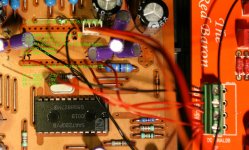
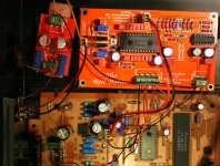
This is as far as I came. Have to get an used osciloscope somewhere, but maybe it's something simple I've overlooked For anyone wanting to take a look there are two images attached; the cd board side and an overlay of cd to Red Baron.
Thanks,
Martin
.Hooked up all the cables, powered up... no smoke. So far so good. Checked the voltages, V digital-analog GND is 0, +15 V is 14.84 V, -5V is -5.59V, +5V is 4.79V. Adjusted the trimmers to 0V offset left and right channels with respect to digital GND and then the same on the DC board with respect to the new left right grounds... connected to the amp, pressed play and... no sound, it's dead silent.
First thing I've checked if the cables supplying FS, clock, data have contact and they are fine.
Then I've checked if the data format is right. Pin 27 OB/TWC is connected to VDD +5V, which means the data format is the same as on my cd player.
Checked if I've connected the output / input wrong.
TDA1541a side:
pin 1 = LS/ WS
pin 2 = BCK
pin 3 = DATA (time multiplexed mode??)
goes to Red Baron I2S input:
pin 1 = BCK
pin 2 = LS/ WS
pin 3 = DATA
I guess this is fine.
and now it's time for more
I've looked at the SAA7220 filter and TDA1541a datasheets, but I don't seem to find the filter would need anything leading back from the dac i.e. the filter does not know the dac is not there.
This is as far as I came. Have to get an used osciloscope somewhere, but maybe it's something simple I've overlooked
For anyone wanting to take a look there are two images attached; the cd board side and an overlay of cd to Red Baron.Thanks,
Martin
Attachments
Guys I will need some help (again)
Hooked up all the cables, powered up... no smoke. So far so good. Checked the voltages, V digital-analog GND is 0, +15 V is 14.84 V, -5V is -5.59V, +5V is 4.79V. Adjusted the trimmers to 0V offset left and right channels with respect to digital GND and then the same on the DC board with respect to the new left right grounds... connected to the amp, pressed play and... no sound, it's dead silent.
First thing I've checked if the cables supplying FS, clock, data have contact and they are fine.
Then I've checked if the data format is right. Pin 27 OB/TWC is connected to VDD +5V, which means the data format is the same as on my cd player.
Checked if I've connected the output / input wrong.
TDA1541a side:
pin 1 = LS/ WS
pin 2 = BCK
pin 3 = DATA (time multiplexed mode??)
goes to Red Baron I2S input:
pin 1 = BCK
pin 2 = LS/ WS
pin 3 = DATA
I guess this is fine.
and now it's time for more
I've looked at the SAA7220 filter and TDA1541a datasheets, but I don't seem to find the filter would need anything leading back from the dac i.e. the filter does not know the dac is not there.
This is as far as I came. Have to get an used osciloscope somewhere, but maybe it's something simple I've overlooked
Thanks,
Martin
Hi Martin,
have you done the NOS Mod. to get the SAA7220 out of the circuit?Servus,
Oliver
Good morning Oliver,
Yes, I've done the nos mod some time ago. The 7220 is physically still there just the out LS/WS, BCK, data are not connected to the dac, but there is a thin wire connecting these three from filter input directly to the dac as done here:
lampizator_DIY NOS Non Over Sampling modification
"""
1. Locate the "LEG 1" on the underside of 1541 and 7220 chips
2. on 7220 cut both traces as close as possible to legs 15 and 16
3. on 1541 cut trace as close as pos on leg 1
4. using a thin wire connect the 1541 and 7220 : leg 1 to 1, 2 to 2, and 3 to 3.
5. connect the 7220 leg 23 to the other chip - the de-modulator chip 7210 leg 11. In case of the Marantz 40/50/60 - there is a newer chip - the 7310 - a square black spider with 44 legs - 11 on each side of the square. The mute is in this case leg 18 (which looks like floating)
6. sit back and listen.
In case of the SAA7220 and SAA7210 chips - if the mute trick does not work, you must float (isolate) the leg 11 on SAA7210 before connecting it to SAA7220P 's leg 23.
"""
aaah, to the Red Baron I2S BCK I should connect the subcode clock at 2,82 Mhz from pin 6 on 7220 instead of connecting pin 2 at 11,29 Mhz xtal which is what I did. Thanks a lot! Have to run (skiing), people are already becoming impatient.... tomorrow evening I am back.
It works
The problem were the five 100 ohm resistors. Seems the BCK signal from my cd-player is weak and got attenuated below a minimum signal threshold. Someone else on the thread had a similar problem and this started my poking with a wire and resistor bypassing. With all five or four resistors in series = no sound. Three resistors in series = weak sound and lots of noise and clicking. With two resistors it works wonderfully.
The sound:
On the cd-player I already had larger mkp bypass capacitors for the dac and nos mod and I did not expect such an improvement. It really stunned me how much more transparent and liquid the sound is. After the cd nos mod, the sound was very analog or brutal like and now it's very smooth, more natural and extremely pleasant to listen to. Haven't done extensive testing yet, but I am already very impressed.... Thanks Oliver for all the help and the amazing Red Baron!!!
and now it's time to enjoy a bit... before the clock upgrade
Martin
- Status
- This old topic is closed. If you want to reopen this topic, contact a moderator using the "Report Post" button.
- Home
- Group Buys
- "Reference" TDA1541A DAC with I2S-BUS architecture